Brooks, Mf series – Brooks Instrument Mfi Series User Manual
Page 31
3-3
Brooks
®
Mf Series
Section 3 Operation
Installation and Operation Manual
X-TMF-Mfi-Mfx-MFC-eng
Part Number: 541B074AAG
August, 2009
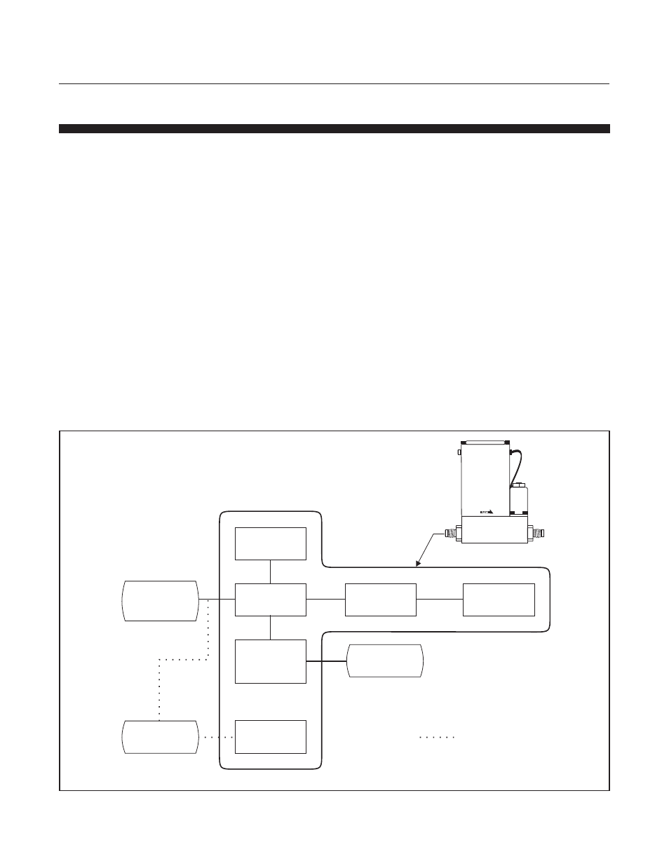
Figure 3-2 Flow Control System Block Diagram
3-3 Zero Adjustment
Each Mf Series controller and meter is factory adjusted to provide a zero
±10 mVdc signal or a 4 mAdc ±.05 mAdc signal at zero flow. The
adjustment is made in our calibration laboratory which is temperature
controlled to 21.1°C (70°F ±2°F). After initial installation and warm-up of
the gas system, the zero flow indication may be other than the factory
setting. This is primarily caused by changes in temperature between our
calibration laboratory and the final installation. The zero flow reading can
also be affected, to a small degree, by changes inline pressure and
mounting attitude.
To check zero, always mount the instrument in its final configuration and
allow a minimum of forty minutes for the temperature of the instrument and
its environment to stabilize. Using a suitable voltmeter or current meter,
check the instrument output signal. If it differs from the factory setting,
adjust it by removing the lower pot hole plug which is located closest to the
instrument body. Adjust the zero potentiometer (refer to Figure 3-4) until
the desired output signal is obtained.
SETPOINT
INPUT
(Voltage or
Current)
VALVE
OVERRIDE
= OPTIONAL
Mf Series
VALVE
DRIVE
0-5 Vdc
Setpoint
COMPARISON
AMPLIFIER
CONTROL
VALVE
5 VOLT
REFERENCE
VALVE
OVERRIDE
LOGIC
COMMAND
POT
FLOW
SENSOR