Brooks, Mf series – Brooks Instrument Mfi Series User Manual
Page 33
3-5
Brooks
®
Mf Series
Section 3 Operation
Installation and Operation Manual
X-TMF-Mfi-Mfx-MFC-eng
Part Number: 541B074AAG
August, 2009
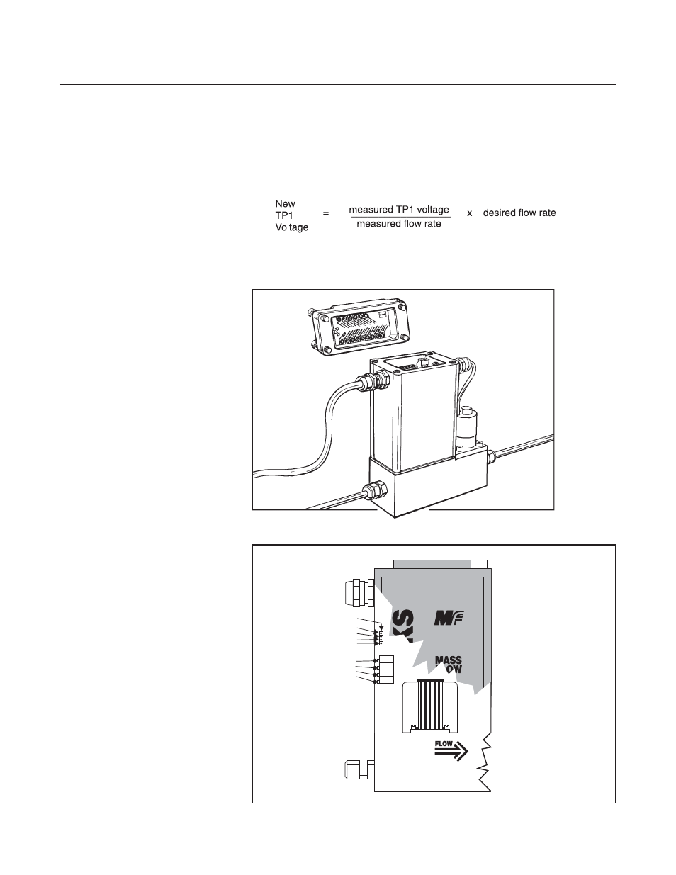
f. Connect the DVM positive lead to TP1 (100x sensor voltage) and the
negative lead to TP4 (circuit common). The setpoint should still be set
at 100% flow (5.000 V). Measure the flow rate using a suitable
volumetric calibration equipment. To adjust the controller to the proper
full scale flow, calculate a new TP1 voltage using the following
equation:
Adjust the span potentiometer until the voltage at TP1 is equal to the
value calculated above. Recheck the flow rate after the flow has
®
TM
SERIES
Span
Linearity
Anticipate
Zero
Test Points:
TP4 Circuit Common
TP3 Valve Voltage
TP2 Lin. Voltage
TP1 Sensor Voltage
(x 100)
Figure 3-4 Adjustment Potentiometer Location
Figure 3-3 Mf Series Calibration Connections
- QMBC (52 pages)
- SolidSense II (28 pages)
- SLA7810/20 (36 pages)
- SLA5810/20 (50 pages)
- SLA5840 (46 pages)
- SLA7840 (40 pages)
- 5866E (65 pages)
- IPS122 2 Indicating Pressure Switches" (18 pages)
- IPT122 2 Indicating Pressure Transmitters" (22 pages)
- 8601 (20 pages)
- PTI Metal Seal Mass Flow Controller w/Real-Time Flow Error Detection & Advanced Diagnostics (82 pages)
- SLA5800 Series (76 pages)
- 5800S Series (50 pages)
- 4800 Series (50 pages)
- 5850EM (74 pages)
- 5851EM (62 pages)
- 5850E (64 pages)
- 5851E (64 pages)
- 5860E (46 pages)
- 5861E (44 pages)
- 5850i (62 pages)
- 5851i (62 pages)
- 5860i (48 pages)
- 5861i (48 pages)
- 5881/91 (40 pages)
- GF40 (78 pages)
- SLAMf Series (76 pages)
- 0254 (124 pages)
- 0260 (14 pages)
- CMC Series (36 pages)
- XacTorr CMX45 (64 pages)
- MT3809G (78 pages)
- MT3809E (72 pages)
- MT3810 (66 pages)
- 3600 Series (56 pages)
- 3750 (64 pages)
- Control Valve (16 pages)
- GT1000 (52 pages)
- 1100 Series (52 pages)
- 1307 (18 pages)
- 1358 (44 pages)
- 1350 (46 pages)
- 1250 (2 pages)
- FC8800 Series (48 pages)