Brooks, Mf series – Brooks Instrument Mfi Series User Manual
Page 13
1-5
Section 1 Introduction
Brooks
®
Mf Series
Installation and Operation Manual
X-TMF-Mfi-Mfx-MFC-eng
Part Number: 541B074AAG
August, 2009
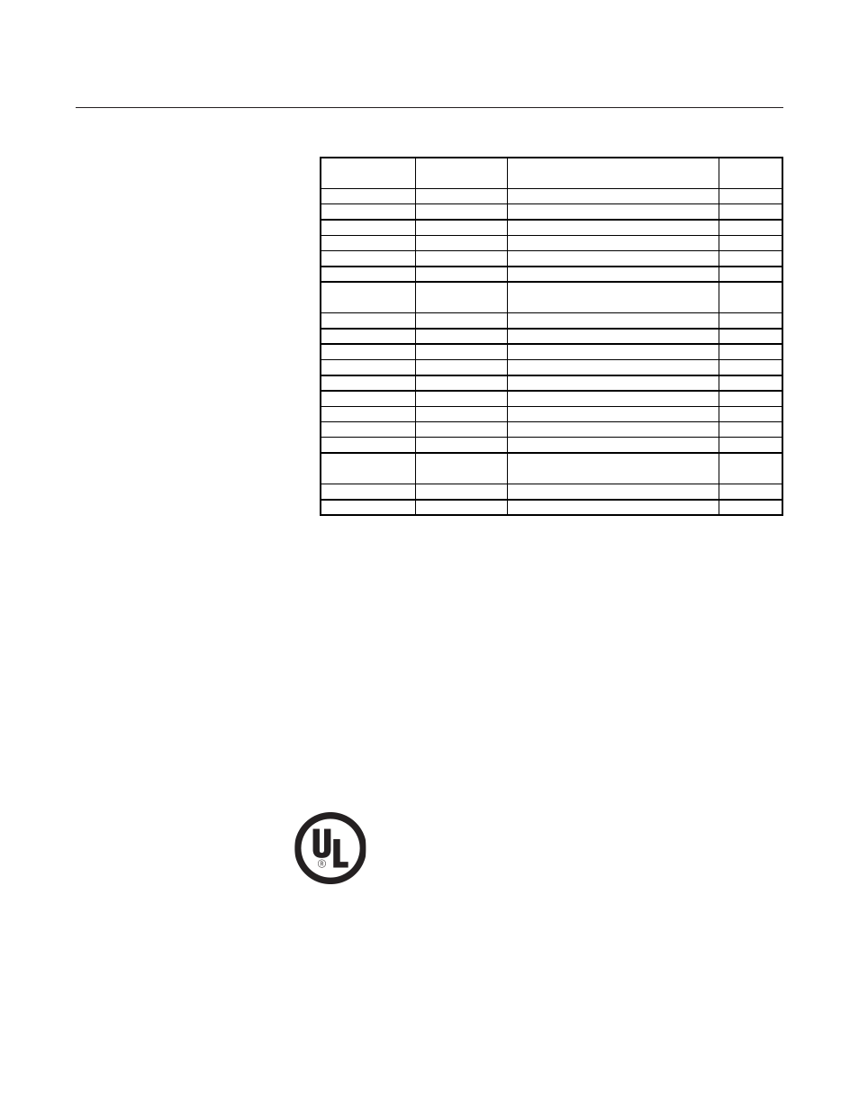
Table 1-3 Mf Series Controllers and Meters Terminal Strip Hookup
Certifications:
EMC Directive 89/336/EEC:
Per EN 61326
Hazardous Location Classification
Non-Incendive
Enclosure Type 4X 1/IP66
Ambient Temperature: 5
0
C > Tamb < 65
0
C (T3C) or
5
0
C > Tamb < 55
0
C (T4)
United States and Canada
UL Listed: E73889 Volume 1, Section 17
UL Recognized: E73889 Volume 3, Section 1
Class I, Division 2, Groups A, B, C and D;
Class II, Division 2, Groups F and G;
Suitable for Class III, Division 2
Per UL 1604 and CSA-213
Pressure Equipment Directive (97/23/EC)
See Table 1-1 for further information
TB-1
Label
Function
Color
Terminal 1-6
Identification
Code**
1
VSUP
Supply Voltage Plus (+) See Table 3
Orange
2
SUPCOM
Supply Voltage Common
Grn/Blk
3
NC
Not Used
Blue
4
SUPCOM
Signal Common
Org/Blk
5
VSIG
Voltage Signal Output
White
6
ISIG
Current Signal Output
Green
TB-2
Label
Function
Color
Terminal 1-9
Identification
Code**
1
NC
Not Used
Blu/Wht
2
GND
Chasis Ground
Grn/Wht
3
NC
Not Used
Red
4
VREF
Reference Output +5 Vdc
Blu/Blk
5
VOR
Valve Override Input
Blk/Wht*
6
NC
Not Used
Red/Wht
7
CMDCOM
Command Common
Black*
8
VCMD
Voltage Command Input (Setpoint)
Red/Blk*
9
ICMD
Current Command Input (Setpoint)
Wht/Blk*
TB-3
Label
Function
Color
Terminal 1 & 2 Identification
Code**
1
NONE
Valve Hookup
Orange*
2
NONE
Valve Hookup
Orange*
*These connections used only for controllers (Models Mf50, Mf51 and Mf53)
**Brooks reference