Brooks, Mf series – Brooks Instrument Mfi Series User Manual
Page 48
4-10
Brooks
®
Mf Series
Section 4 Maintenance &
Troubleshooting
Installation and Operation Manual
X-TMF-Mfi-Mfx-MFC-eng
Part Number: 541B074AAG
August, 2009
3. For Mf51/61, place the end block O-ring in position and install the end
block with the 4 hex socket screws.
4. (Mfi Series only), press the lubricated sensor O-rings (25B) into the flow
controller body. Install the sensor assembly and secure with two screws
(37) and washers (38) and tighten.
5. Install the orifice (33) and its O-ring (25A) using a 3/8 nut driver. Insure
that the orifice is fully seated but do not overtighten.
6. Insert the valve preload spacers (28A), if used, into the valve cavity in
the flow controller body. Use care to preserve the correct order.
7. Place the spacers (28B) and springs (29) on the valve seat (32) in the
same order as noted in Step 8 of the disassembly. Screw the valve seat
(32) into the plunger (26). Tighten the assembly until there is no
looseness but do not overtighten.
8. Install the valve plunger assembly (26, 29, 28B and 32) on the preload
spacers (28A). Install air gap spacers (28A), if used, on top of the valve
springs.
9. Install the valve stem assembly (24), secure with the valve retaining
plate (23) and four hex socket screws (22). Install O-ring (1) onto valve
stem (24). When installing the screws they should first make light
contact with the plate which should be checked to insure that it makes
full contact around the stem assembly. Torque the screws securing the
valve retaining plate in a diagonal pattern (refer to Figure 4-1) to
17 in/lbs
End
Valve
Electronics
Electronics
Block
Retaining
Sensor
Housing
Dome
Housing Cover
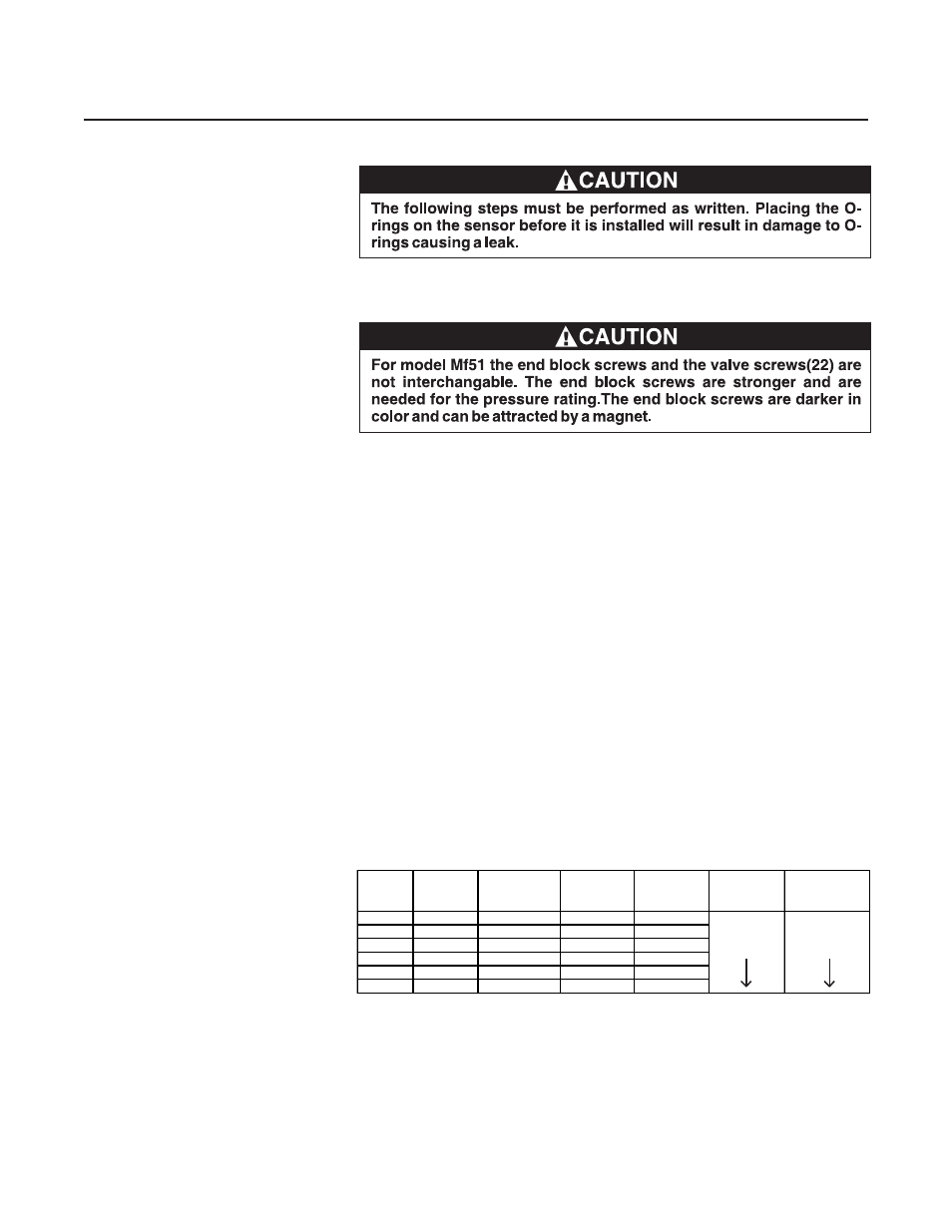
Model No.
Screws
Plate Screws
Screws
Screws (M4)
Nuts**
Screws
Mf50
N/A
17
15
25
1 1/2 Turns
Tighten until
Mf60
N/A
N/A
17
25
past finger
cover contacts
Mf51
30
17
10
25
tight
housing
Mf61
30
N/A
10
25
Mf53
133
17
10
25
Mf63
133
N/A
10
25
N/A = Not applicable
* The torque values listed should be used as a guide for assembly. The actual
torque may need to be adjusted depending on the lubrication of the mating
threads. It is recommended that the fasteners are used only one time. New
fasteners can be obtained as spare parts from the factory (refer to Section 5).
** This should be used only as a guide. It is recommended that the actual
number of turns, or torque, be determined empirically, using the actual cable.
Table 4-3 Mf Series Torque Requirements