Brooks, Mf series – Brooks Instrument Mfi Series User Manual
Page 47
4-9
Brooks
®
Mf Series
Section 4 Maintenance &
Troubleshooting
Installation and Operation Manual
X-TMF-Mfi-Mfx-MFC-eng
Part Number: 541B074AAG
August, 2009
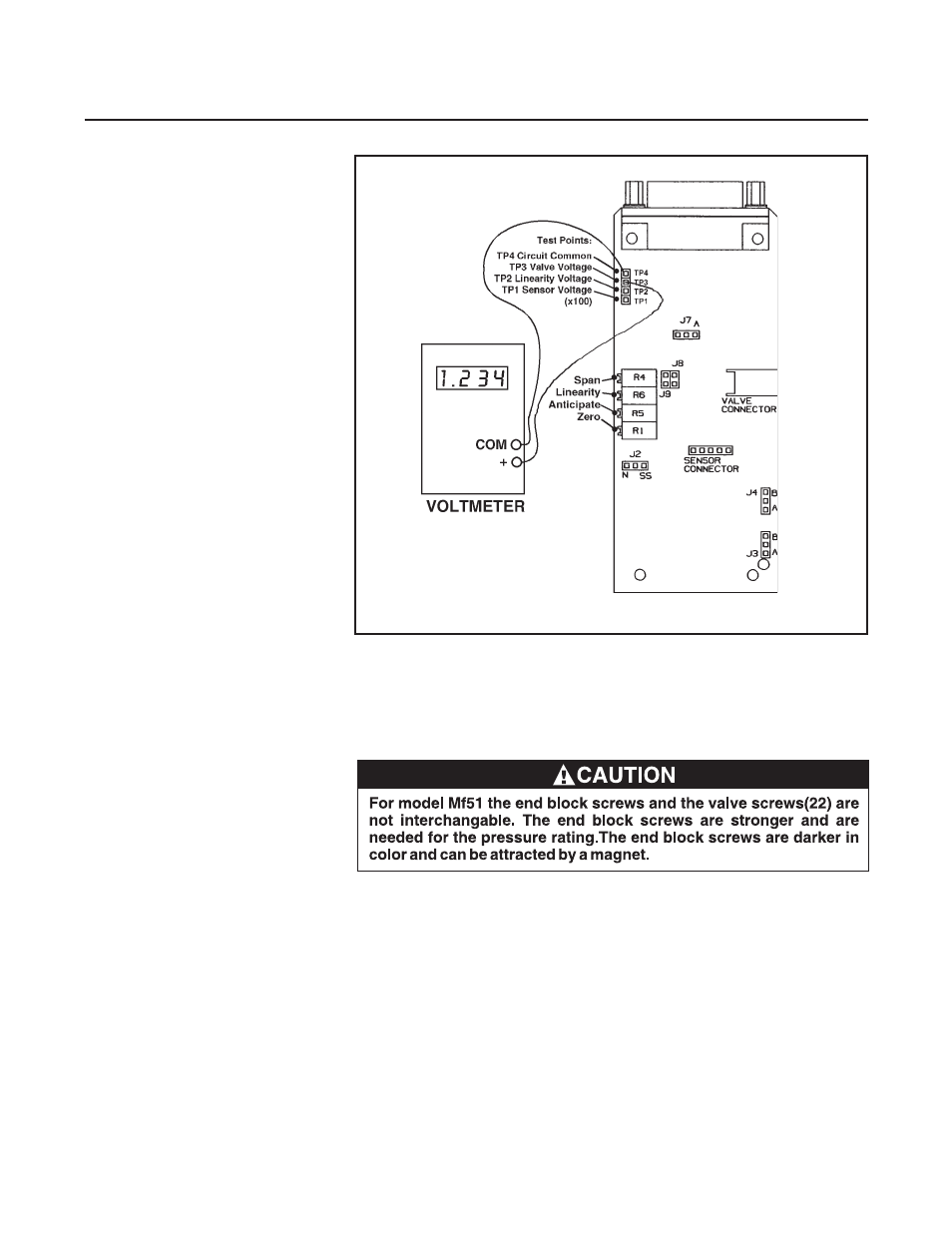
Figure 4-2 Voltmeter Connections for Valve Adjustment
17.For Mf51/61, remove the four screws from the end block and carefully
remove the end block.
B. Assembly (Mfx Series sensor assembly is not removable)
Note: It is recommended that all service O-rings be replaced during
instrument assembly. All service O-rings should be lightly lubricated with
Fomblin lubricant (part of service O-ring kit, Section 5) prior to their
installation.
Note: Torque valves for all critical fasteners are listed in Table 4-3.
1. Examine all parts for signs of wear or damage, replace as necessary.
2. Place the restrictor O-ring on the restrictor assembly. Screw the
restrictor assembly into the inlet side of the flow controller body using
the restrictor tool, tighten hand tight.
- QMBC (52 pages)
- SolidSense II (28 pages)
- SLA7810/20 (36 pages)
- SLA5810/20 (50 pages)
- SLA5840 (46 pages)
- SLA7840 (40 pages)
- 5866E (65 pages)
- IPS122 2 Indicating Pressure Switches" (18 pages)
- IPT122 2 Indicating Pressure Transmitters" (22 pages)
- 8601 (20 pages)
- PTI Metal Seal Mass Flow Controller w/Real-Time Flow Error Detection & Advanced Diagnostics (82 pages)
- SLA5800 Series (76 pages)
- 5800S Series (50 pages)
- 4800 Series (50 pages)
- 5850EM (74 pages)
- 5851EM (62 pages)
- 5850E (64 pages)
- 5851E (64 pages)
- 5860E (46 pages)
- 5861E (44 pages)
- 5850i (62 pages)
- 5851i (62 pages)
- 5860i (48 pages)
- 5861i (48 pages)
- 5881/91 (40 pages)
- GF40 (78 pages)
- SLAMf Series (76 pages)
- 0254 (124 pages)
- 0260 (14 pages)
- CMC Series (36 pages)
- XacTorr CMX45 (64 pages)
- MT3809G (78 pages)
- MT3809E (72 pages)
- MT3810 (66 pages)
- 3600 Series (56 pages)
- 3750 (64 pages)
- Control Valve (16 pages)
- GT1000 (52 pages)
- 1100 Series (52 pages)
- 1307 (18 pages)
- 1358 (44 pages)
- 1350 (46 pages)
- 1250 (2 pages)
- FC8800 Series (48 pages)