Warning, Brooks, Mf series – Brooks Instrument Mfi Series User Manual
Page 10
1-2
Brooks
®
Mf Series
Section 1 Introduction
Installation and Operation Manual
X-TMF-Mfi-Mfx-MFC-eng
Part Number: 541B074AAG
August, 2009
and positions the precision solenoid control valve. When the command
signal is below 1% of full scale, the control valve is positioned to fully
closed. The control valve can be latched fully open or closed by activating
the valve override circuit.
1-4 Specifications
Do not operate this instrument in excess of the specifications
listed below. Failure to heed this warning can result in serious
personal injury and/or damage to the equipment.
WARNING
PERFORMANCE CHARACTERISTICS:
*
Standard temperature and pressure equals 0°C and 101kPa (760 Torr).
These mass flow controllers and meters can be calibrated to other
conditions. Specify at time of ordering.
Control/Usable Range
50 to 1
Accuracy
±1% full scale including linearity at calibrated conditions
±1.5% full scale including linearity for Mf50 and Mf60 for flow ranges
greater than 20 slpm
Table 1-1 Flow Ranges
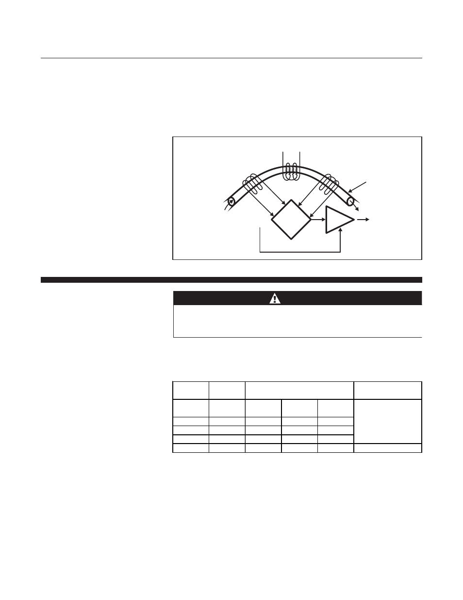
Figure 1-1 Principle of Operation.
+ Vdc
Flow
Amplifier
Heater
0-5 Vdc
and
4-20 mA
Bypass
Sensor Tube
T2
Downstream
Temperature
Sensor
To Power Supply
T1
Upstream
Temperature
Sensor
Bridge
for
T Detection
Δ
Mass Flow
Mass Flow
Flow Ranges
PED
Controller
Meter
Nitrogen*
Module H
Model
Model
Min. F. S.
Max. F. S.
Max. Press.
(slpm)
psi (Bar)
Mf50
Mf60
0.003
30
1500 (100)
SEP
N/A
Mf61
0.003
30
4500 (300)
Mf51
Mf63
10
100
1000 (68)
Mf53
N/A
100
1000
1000 (68)
1 for all 150 lbs.Flanges