Brooks, Mf series, Caution – Brooks Instrument Mfi Series User Manual
Page 21
2-3
Brooks
®
Mf Series
Section 2 Installation
Installation and Operation Manual
X-TMF-Mfi-Mfx-eng
Part Number: 541B074AAG
August, 2009
2-7 Gas Connections
Refer to Tables 5-1 through 5-4 for the available process connection types
and sizes. It is recommended that good tubing and piping practice be
followed. It is also recommended that for very low flows in meter size
Mf50's that tubing 1/4 or less be used and for flows over 10 slpm 3/8 tubing
be applied. Prior to installation, make certain all piping is clean and free of
obstructions. Install the piping in such a manner that permits easy removal
if the instrument is to be removed for cleaning or test bench
troubleshooting.
2-8 In-Line Filter
It is recommended that an Brooks in-line filter (refer to DS-5848 for
appropriate models/flows) be installed upstream from the instrument to
prevent the possibility of any foreign material entering the flow sensor or
control valve. The filtering element should be periodically replaced or
ultrasonically cleaned.
For Models Mf53/63, an in-line filter of 100 microns standard has been
installed upstream from the meter or controller to prevent the possibility of
any foreign material entering the flow sensor or control valve. The filtering
element should be periodically replaced or ultrasonically cleaned.
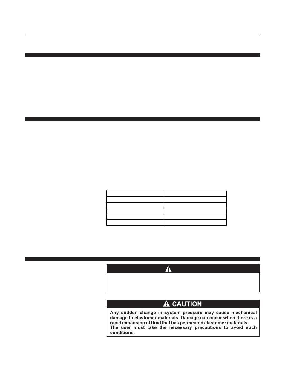
Note: The above lists the max. recommended porosity for each flow range.
It is recommended that the minimum micron porosity that does not limit the
full scale flow rate be used.
2-9 Installation (Refer to Table 1-4, Figure 1-4, 2-1 and Quick Start Instructions)
When installing the controller, care should be taken that no
foreign materials enter the inlet or outlet of the instrument. Do not
remove the protective end caps until time of installation.
CAUTION
Table 2-1 Recommended Filter Size
Maximum Flow Rate
Recommended Filter Size
100 sccm
1 micron
500 sccm
2 micron
1 to 5 slpm
7 micron
10 to 30 slpm
15 micron
30 to 100 slpm
30 micron