Brooks, Mf series – Brooks Instrument Mfi Series User Manual
Page 34
3-6
Brooks
®
Mf Series
Section 3 Operation
Installation and Operation Manual
X-TMF-Mfi-Mfx-MFC-eng
Part Number: 541B074AAG
August, 2009
stabilized for at least two minutes. Repeat this check and adjustment
procedure until the measured flow rate is within 1% of the desired flow
rate.
Note: The voltage at TP1 is 100 times the output voltage of the sensor.
This voltage can range from 1.2 to 12 Volts, however, it is
recommended that this voltage stays between 2.0 and 9.0 Volts for
proper operation. If the recommended voltage range exceeds that
desired, accuracy and/or signal stability may not be achieved. If one of
the limits is reached, check the orifice and restrictor sizing procedures.
Refer to Sections 4-5 and 4-6 respectively.
g. Adjust the controller setpoint for 0% flow/shut-off the flow to the meter.
Connect the DVM positive lead to 0-5 V signal output (TB-1, Terminal 5)
and the negative lead to TP4. Readjust the zero potentiometer for an
output of 0 mV ±2 mV as necessary.
h. Adjust the controller setpoint/adjust flow rate to the meter for 50% flow,
and measure the flow rate. Calculate the error as a percentage of full
scale.
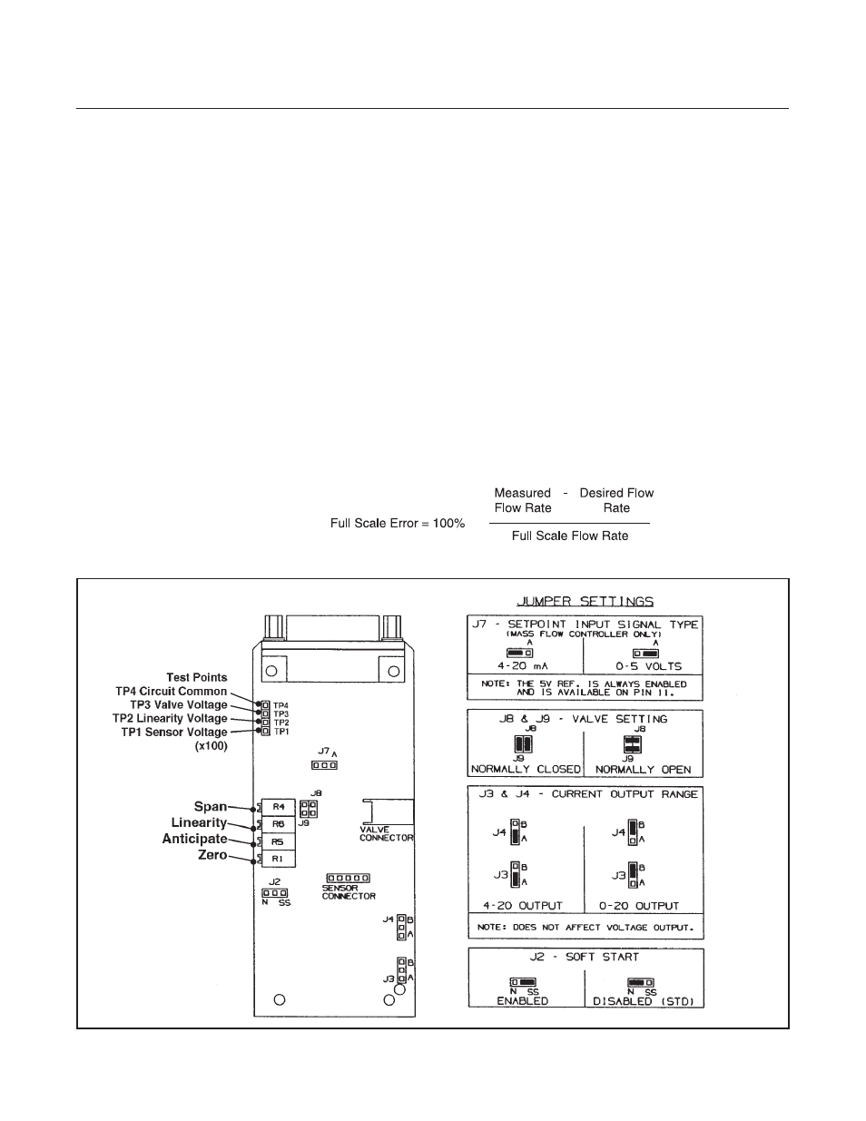
Figure 3-5 PC Board Jumper Location & Function