Brooks, Mf series – Brooks Instrument Mfi Series User Manual
Page 54
4-16
Brooks
®
Mf Series
Section 4 Maintenance &
Troubleshooting
Installation and Operation Manual
X-TMF-Mfi-Mfx-MFC-eng
Part Number: 541B074AAG
August, 2009
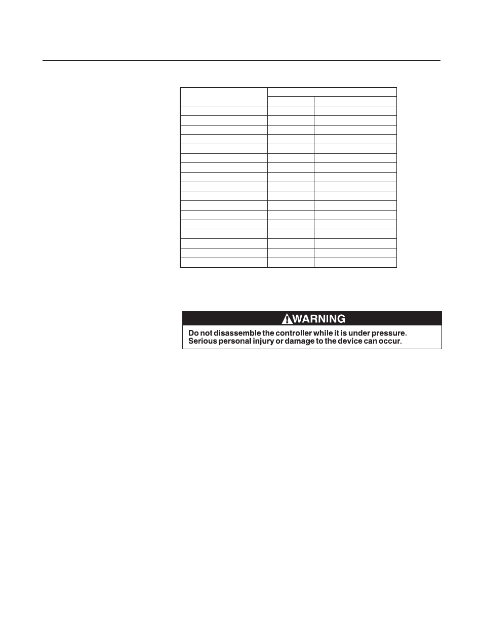
Orifice Size (inches)
Minimum Flow Rate (sccm)
32°F (0°C)
70°F (21.1°C)
0.0013
5.3
(5.7)
0.002
12.5
(13.5)
0.003
39.2
(42.2)
0.004
82.5
(88.9)
0.0055
190
(205)
0.007
374
(403)
0.010
748
(806)
0.014
1364
(1469)
0.020
2673
(2879)
0.032
6490
(6991)
0.048
12980
(13980)
0.062
22000
(2879)
0.078
31900
(34400)
0.093
42500
(45800)
0.120
69300
(74700)
0.1405
95,500
(103,000)
0.1495
108,200
(116,600)
Inlet Pressure = 10 psig
Outlet Pressure = 10 inches of water (0.4 psig) or less
Note: Flow Rate based on Nitrogen
5. I f the measured flow exceeds the value shown in Table 4-4 proceed to
step 7.
If the flow is less than expected, depressurize the controller and
disassemble the valve following Disassembly, Section 4-4 and proceed to
step 6.
Note: If the orifice size in use is unknown, it can be determined by:
Refering to Section 4-7, Orifice Sizing.Opening the control valve and
inspecting the orifice. Refer to Section 4-4, Disassembly
Consulting the factory with the full model number which is printed on the
front label of the controller and the order.
6.For orifice sizes 0.007" and greater add a 0.005" thick larger diameter
flow clearance spacer.
For orifice sizes less than 0.007" add a larger diameter 0.005" thick large
diameter flow clearance spacer and two 0.002" thick small diameter flow
clearance spacers. Refer to Figure 4-3b for spacer placement.
If this does not provide adequate flow, remove one at a time, 0.002"thick
small diameter spacers until the correct flow is achieved.
Assemble the valve following Assembly Section 4-4, utilizing the old socket
head cap screws and the 020 elastomeric O-ring. Apply inlet pressure and
zero volts to the valve.
Table 4-4 Orifice Capacities