Brooks, Mf series – Brooks Instrument Mfi Series User Manual
Page 35
3-7
Brooks
®
Mf Series
Section 3 Operation
Installation and Operation Manual
X-TMF-Mfi-Mfx-MFC-eng
Part Number: 541B074AAG
August, 2009
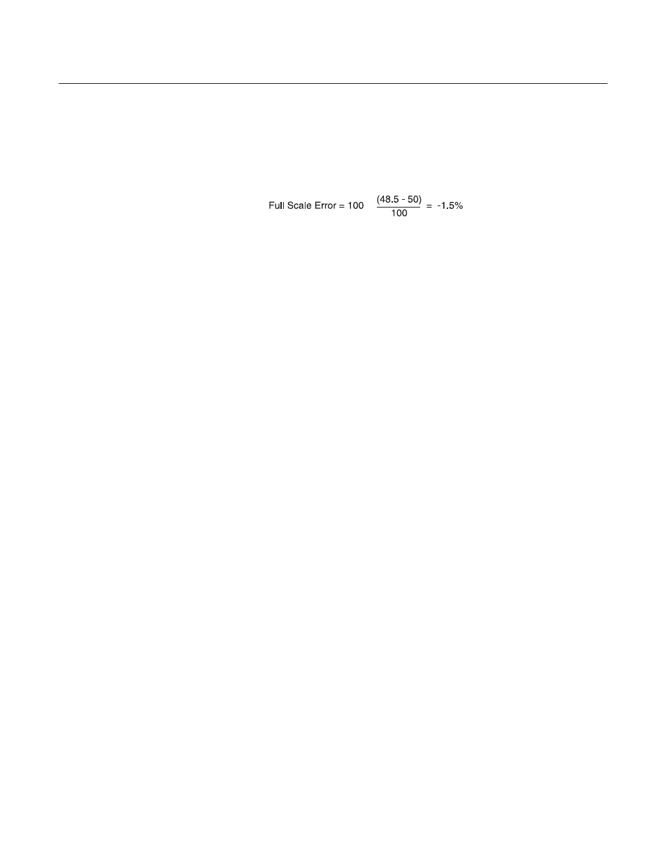
Example:
What is the percent of full scale error when full scale is equal to 100
sccm?
Measure flow rate = 48.5 sccm
Desired flow rate = 50.0 sccm
i. Calculate the TP2 correction voltage:
(error recorded in Step h) x 0.450 Volts
Example:
Error = -1.5%
TP2 correction voltage = -1.5 x 0.450 = -0.675 Volts
New TP2 voltage = 0 Volts + (-0.675) = -0.675 Volts
j. Adjust the setpoint for 100% flow. Connect the DVM positive lead to
TP2 and the negative lead to TP4.
k. Adjust the linearity potentiometer for an output equal to the new
calculated TP2 voltage.
l. Repeat Steps f, g and h.
1. If the error recorded in Step h is less than 0.5%, then the calibration
procedure is complete.
2. If the error is greater than 0.5% adjust the setpoint for 100%
(5.000V). Connect the DVM positive lead to TP2 (linearity voltage)
and the negative lead to TP4 (circuit common).
Calculate a new TP2 voltage as follows:
error
Measured
New TP2 voltage = recorded in
x 0.450 V
+
TP2
Step i
voltage
Example:
Controller error = 0.7%
Measured TP2 voltage = -0.567 Volts
TP2 correction = 0.7 x 0.450 = 0.315 Volts
New TP2 correction = 0.315 Volts + (-0.567) = -0.252 Volts
Adjust the linearity potentiometer for an output equal to the new TP2
voltage and then repeat Steps f, g and h.
Note: The voltage at TP2 can range from -10 to +3 Volts, however, it
is recommended that this voltage stays between -2.5 and +2.5 Volts
for proper operation. If the recommended voltage range is
exceeded, the desired accuracy and/or signal stability may not be
achieved. If one of the limits is reached, check the restrictor sizing.
Refer to Section 4-5.