Quick-start operating instructions – Dynasonics TFXM Series Ultrasonic Multi-Channel Flow Meter User Manual
Page 5
Rev. 8/02
-1. 4-
TFXM
2. PIPE PREPARATION AND TRANSDUCER MOUNTING
A. The piping surface where the transducers are to be
mounted needs to be clean and dry. Remove loose scale,
rust and paint to ensure satisfactory acoustical bonds.
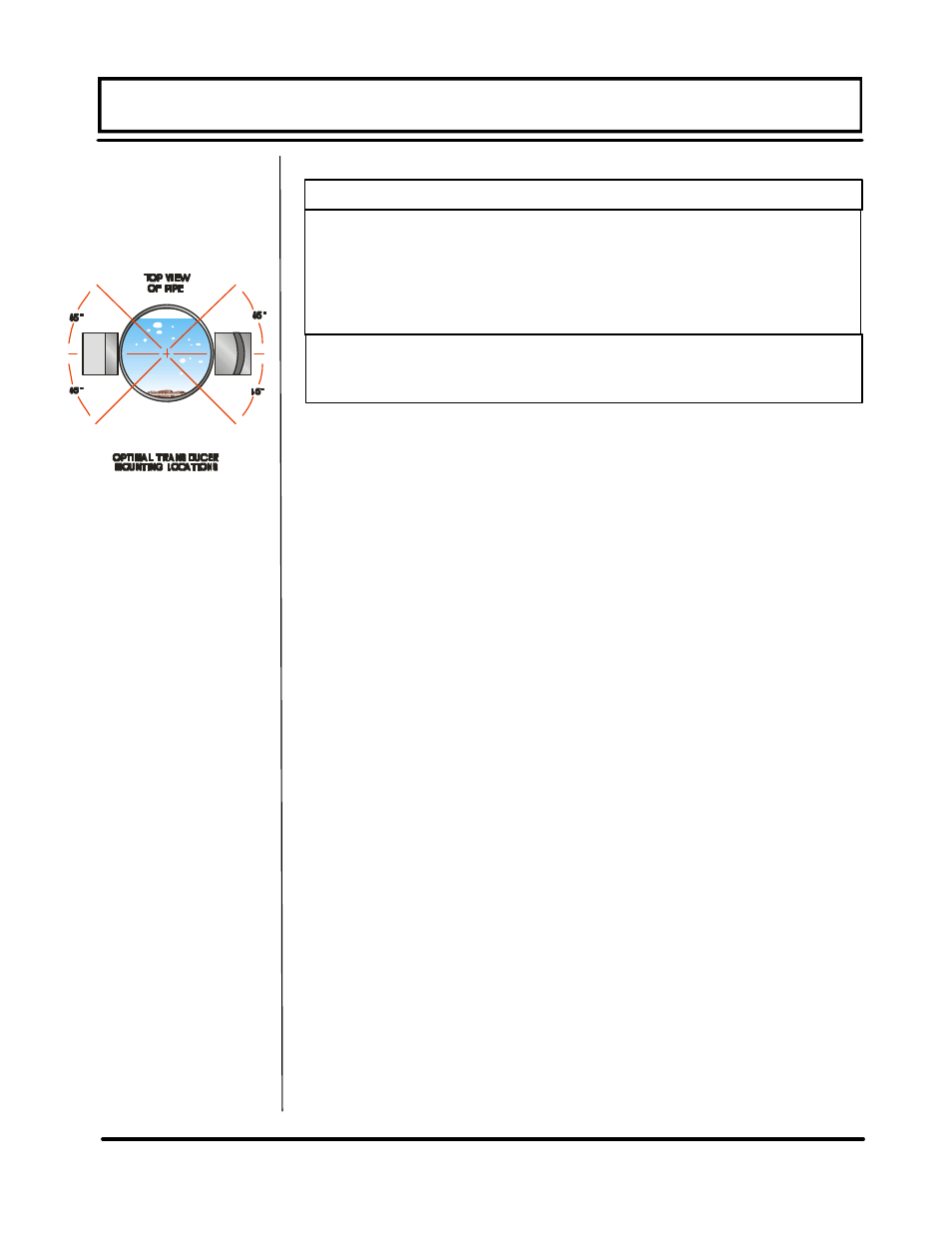
B. Apply a 3/8” [8 mm] wide bead of couplant lengthwise onto
the transducer faces. Place each transducer onto the pipe
ensuring proper linear and radial placement.
C. Tighten the transducer mounting straps sufficiently to
squeeze the couplant out along the flat surface of the trans-
ducer, filling the void between the transducer and the pipe
wall.
3. TRANSDUCER/POWER CONNECTIONS
A. If additional cable is to be added to the transducers, utilize
RG59 (75 Ohm) cable splices and ensure that both cables
are of equal length.
B. Refer to the TFXM Field Wiring Diagram, Figure 1.4, and
the terminal block labels for proper power and transducer
connections. Verify that the voltage level listed on the
product identification label—located on the side of the in-
strument enclosure– matches the power source where
connection is being made.
4. INITIAL SETTINGS AND POWER UP
A. Apply power to the instrument.
B. Verify that SIG STR is greater than 2% on all channels .
C. Verify that measured liquid SSPD is within 0.5% of the
configuration value on all channels.
D. Input proper units of measure and I/O data.
Startup
Connections
QUICK-START OPERATING INSTRUCTIONS
1.
Transducer mounting method
2.
Pipe O.D. (Outside Diameter)
3.
Pipe wall thickness
4.
Pipe material
5.
Pipe sound speed*
6.
Pipe relative roughness*
7.
Pipe liner thickness
8.
Pipe liner material
9.
Fluid type
10. Fluid sound speed*
11. Fluid viscosity*
12. Fluid specific gravity*
* Nominal values for these parameters are included within the TFXM
operating system. The nominal values may be used as they appear or
may be modified if exact system values are known.
TABLE 1.1
Figure 1.2
Transducer
Orientation