Part 1 - transmitter installation, Transducer connections – Dynasonics TFXM Series Ultrasonic Multi-Channel Flow Meter User Manual
Page 10
Rev. 8/02
-1. 9-
TFXM
To access terminal strips for electronic connections, loosen the six
screws in the wiring access panel located on the bottom of the en-
closure.
1. Guide the transducer cables through the transmitter conduit
holes located in the bottom of the enclosure. Secure the
transducer’s flexible conduit with the supplied conduit nut (if
flexible conduit was ordered with the transducer) or tighten the
cord grip on the coaxial cable.
2. The terminals within TFXM are a screw terminal type. Connect
the appropriate wires to the corresponding screw terminals in
the transmitter. Observe UP/DOWN and CH1 or CH2
orientation. CH1 and CH2 correspond to the measuring chan-
nels contained within the TFXM flow meter. DTFXM1 flow me-
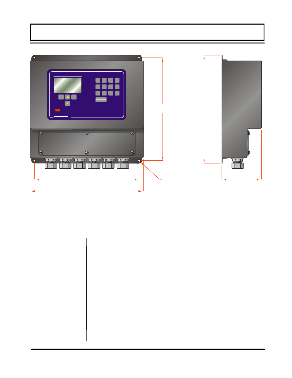
PART 1 - TRANSMITTER INSTALLATION
Figure 1.3 - TFX Transmitter Installation Dimensions
6
2
0
7
3
1
8
4
.
9
5
+/-
10.55
(268.0)
10.44
(265.1)
11.34
(288.0)
4.18
(106.2)
11.00
(279.4)
.20 (5.1) DIA
4 MOUNTING
HOLES
Transducer
Connections