Part 2 - transducer positioning – Dynasonics TFXM Series Ultrasonic Multi-Channel Flow Meter User Manual
Page 36
Rev. 8/02
- 2.21 -
TFXM
3. Secure the transducer by tightening the stainless steel
strap. (Excessive pressure is not required. Apply just
enough pressure so that the couplant fills the gap between
the pipe and transducer.) If DOW 732, or some other sili-
cone RTV type sealant, was used ensure that no relative
movement between the transducer and pipe takes place
during the setting time and do not apply instrument power
for at least 24 hours. If Dow 44 or Dow 111 or an alternate
form of grease has been used as a couplant, setting time is
not necessary.
4. Mount the transducer in the same manner as the first, but at
the second mark on the pipe. Slide the transducer clamp
over the transducer and secure with the stainless strap. Re-
fer to Figure 2.9 for proper orientation.
NOTE: Since pipes larger than 20 inches (500 mm),
typically can be out-of-round by a substantial amount, it
is advised that the second transducer be left loose so
that it can be positioned at the location of greatest Signal
Strength. See Section 3 of this manual for Diagnostics
and Signal Strength Measurement. Maximum Signal
Strength can typically be obtained within 1 inch [25 mm]
of the calculated lineal distance.
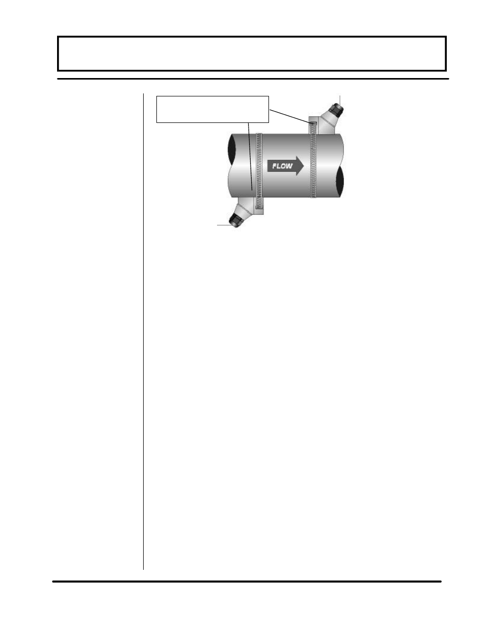
PART 2 - TRANSDUCER POSITIONING
Figure 2.9 Z-Mode Transducer Mounting
Lineal measurements are
made from these lines.