Dynasonics TFXM Series Ultrasonic Multi-Channel Flow Meter User Manual
Page 102
Description: Installation and Operation Manual Addendum
Series TFX Heat Flow Meter
Origin Date: 02/10/00
Revision: none
Revision date: none
Page 2 of 3
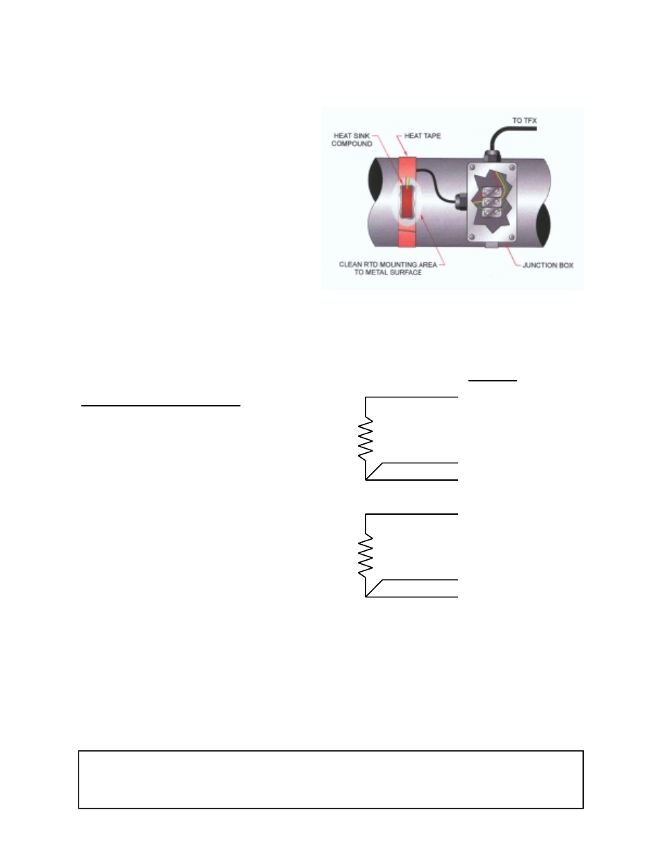
3. Place a small amount of heat sink
compound on the pipe in the RTD
installation location. See Figure 1.
Press the RTD firmly into the com-
pound. Fasten the RTD to the pipe
with the included heater tape.
4. Route the RTD wires to an electrical
junction box in close proximity to the
installation location. Secure the RTD
wires such that they will not be pulled
on or abraded inadvertently. Re-
place the insulation on the pipe.
5. Route a cable from the electrical
junction box back to the TFX flow-
meter. Connect the RTDs as illus-
trated in Figure 2. Note that the
SNS1 and DRV1 wires originate from
the same location on the RTD.
Transmitter Programming
1. The RTDs included with the TFX heat
delivered flowmeter have been factory
calibrated and are marked with an
identification as to which terminal, #1
or #2, the RTD has been calibrated.
If recalibration of the RTDs is required
or RTDs other than those supplied
with the TFX are being utilized, the
UltraLink software utility will be re-
quired. UltraLink can also be used to
configure all operating parameters of
the heat flow instrument.
2. To properly measure heat delivery,
the specific heat capacity of the liquid
must be entered. When a liquid is
chosen from the FL TYPE list, a de-
fault specific heat will be loaded. This default value is displayed as SP HEAT in the
BASIC MENU. If the actual specific heat of the liquid is known or if it differs from
the default value, press the ENTER key and modify the value. Press the enter key
to save the value. See the values listed in Tables 1 and 2 for specific values. Enter
a value that is the mean of both pipes.
RTD#1
REF1+2 & RTN
SNS 1
DRV 1
RTD#2
REF1+2 & RTN
SNS 2
DRV 2
TFX Module
Figure 2
Figure 1