Part 2 - transducer positioning – Dynasonics TFXM Series Ultrasonic Multi-Channel Flow Meter User Manual
Page 35
Rev. 8/02
- 2.20 -
TFXM
Transducer Mounting
1.
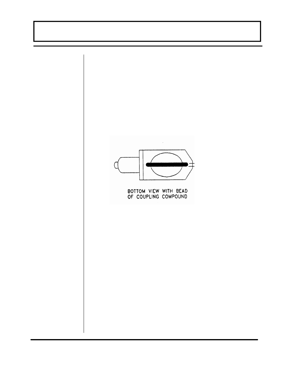
Place a single bead of couplant, approximately 3/8 inch [6
mm] thick, on the flat face of the transducer. See Figure
2.8. Use Dow 732 for permanent and Dow 44 or Dow 111
for temporary (less than 12 months) installations. [For high
temperature installations, utilize the Dow 112 and orange
silicone pads that were shipped with the DTTH transduc-
ers. Apply the couplant to the transducer face as shown in
Figure 2.8, then place the silicone pad over the couplant.
Apply the couplant to the exposed surface of the silicone
pad.
2.
Install the first transducer on the pipe, with the alignment
groove placed over one of the marks created in the previ-
ous section. The stainless steel clamping band will be po-
sitioned within the groove on the front of the transducer.
See Figure 2.9.
PART 2 - TRANSDUCER POSITIONING
Figure 2.8 Transducer Couplant Application