Color cameras, Description of the data path, Figure 38: block diagram color camera – ALLIED Vision Technologies Guppy PRO F-503 User Manual
Page 97: Guppy pro technical manual v4.0.0
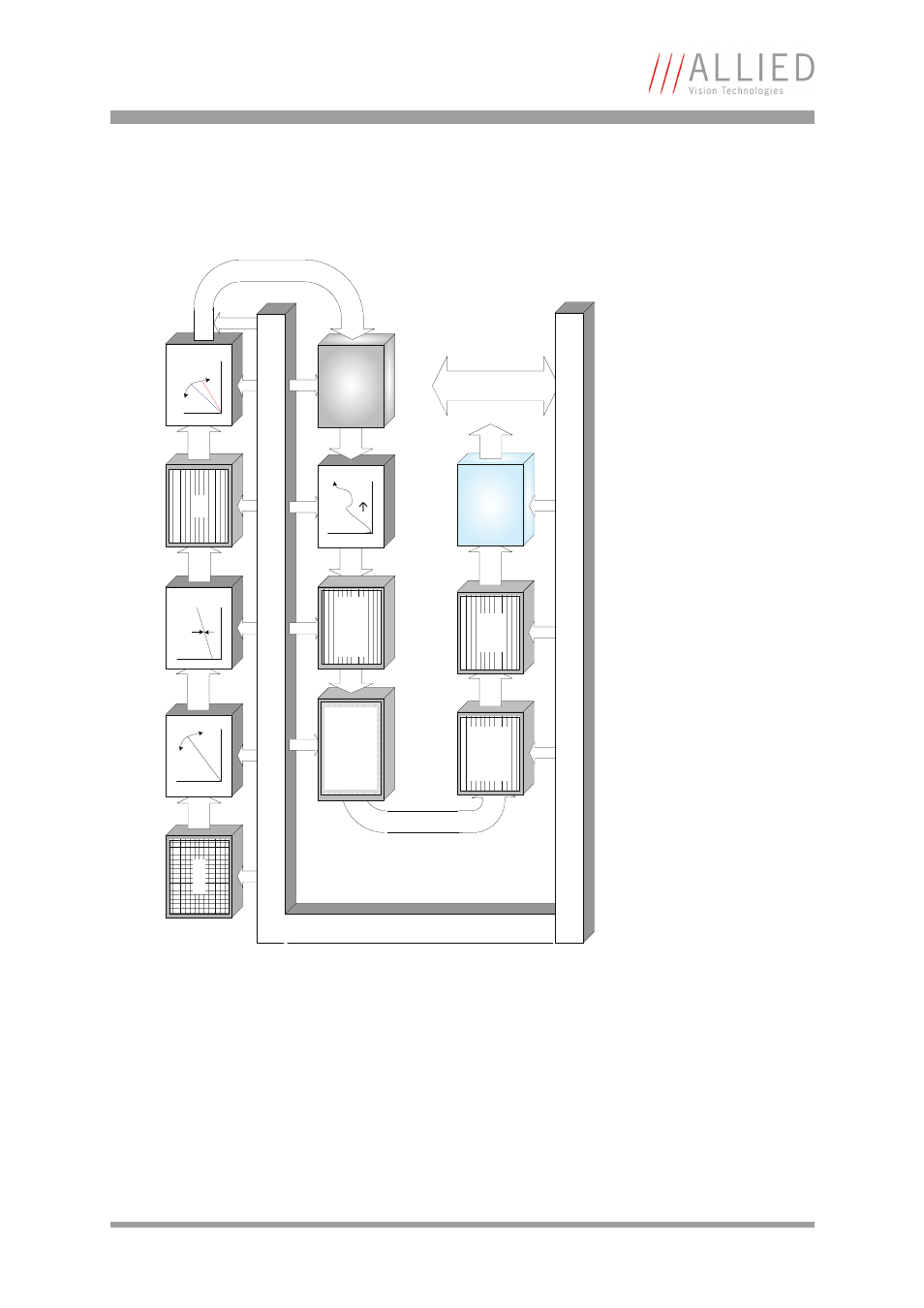
Description of the data path
Guppy PRO Technical Manual V4.0.0
95
Color cameras
Setting LUT = OFF effectively makes full use of the 14 bit by bypassing the LUT circuitry; set-
ting LUT = ON means that the most significant 12 bit of the 14 bit are used and further down
converted to 10 bit. For cameras with 12-bit ADC: the most significant 10 bit of the 12 bit are
used.
Figure 38: Block diagram color camera
Sensor
Analog
Gain
Analog
Offset
Analog
14 bit
White balance
HIROSE I/O
RS232
Test-Pattern
8 bit
Camera control
14 bit
LUT
12
10
14
b
it
Defect pixel
correction
(only CMOS)
14 bit
Horizontal
masking
(only CCD)
ADC
CMO
S: t
he fo
llo
wing
functions are
i
n
te
grated in
senso
r:
Sub-sa
mplin
g, ho
rizontal
maskin
g
Hue
Saturation
Color correction
Color conversion
8 bit
Color
interpolation
8 bit
Frame
memory
8 b
it
IEEE 1394b
interface
13
94
b
Camera control
*
* Some Guppy PRO models
deliver 12 bit only.