Camera interfaces, Ieee 1394b port pin assignment, Chapter – ALLIED Vision Technologies Guppy PRO F-503 User Manual
Page 72
Camera interfaces
Guppy PRO Technical Manual V4.0.0
70
Camera interfaces
This chapter gives you detailed information on status LEDs, inputs and out-
puts, trigger features and transmission of data packets.
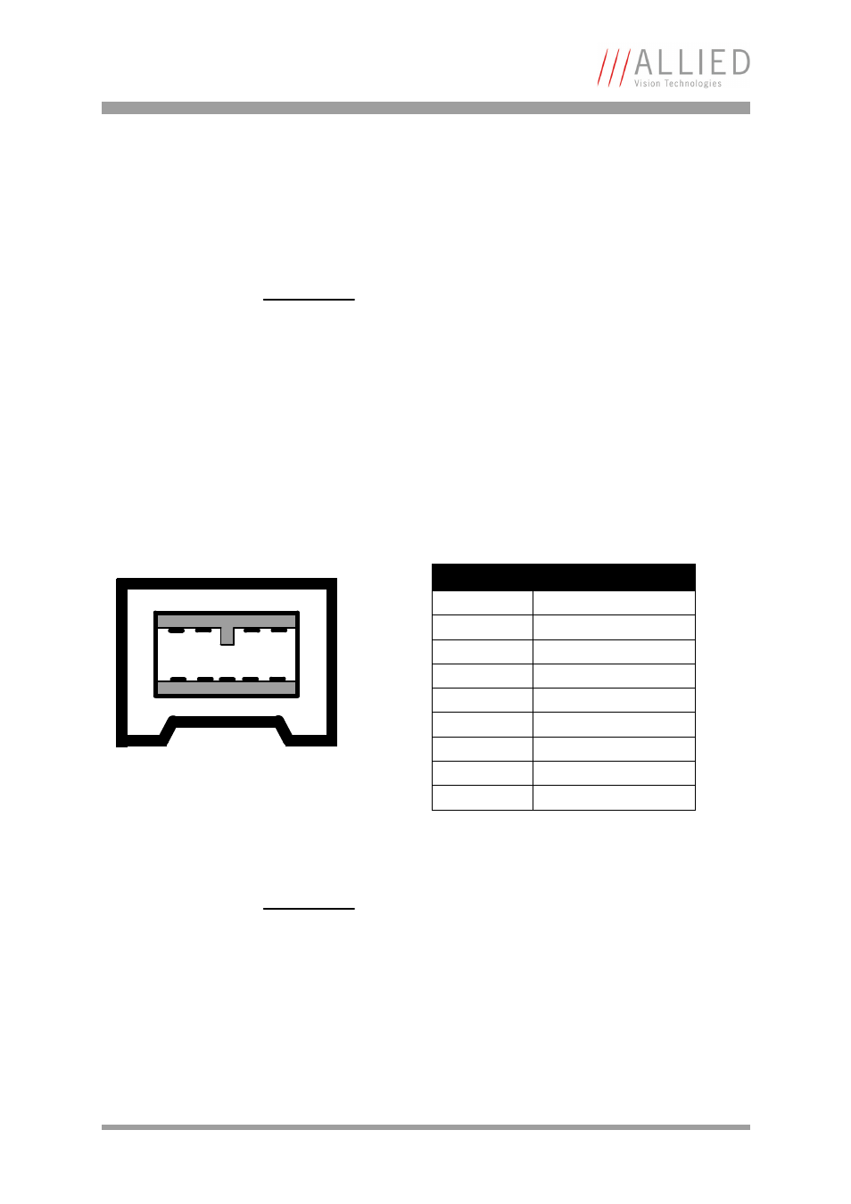
IEEE 1394b port pin assignment
The IEEE 1394b connector is designed for industrial use and has the following
pin assignment as per specification:
Note
For a detailed description of the camera interfaces
(FireWire, I/O connector), and operating instructions see
the Hardware Installation Guide, Chapter Camera inter-
faces.
Read all Notes and Cautions in the Hardware Installation
Guide, before using any interfaces.
Figure 27: IEEE 1394b connector
Note
•
IEEE 1394b connectors with screw lock mechanism
provide access to the IEEE 1394 bus and thus makes it
possible to control the camera and output frames.
1
2
3
4
5
6 7
8
9
Pin
Signal
1
TPB-
2
TPB+
3
TPA-
4
TPA+
5
TPA (Reference ground)
6
VG (GND)
7
N.C.
8
VP (Power, VCC)
9
TPB (Reference ground)