Control and video data signals, Inputs, Triggers – ALLIED Vision Technologies Guppy PRO F-503 User Manual
Page 77
Camera interfaces
Guppy PRO Technical Manual V4.0.0
75
Control and video data signals
The inputs and outputs of the camera can be configured by software. The dif-
ferent modes are described below.
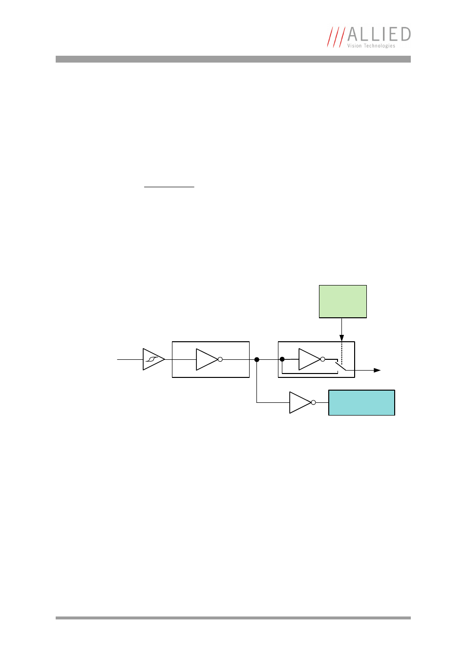
Inputs
The optocoupler inverts all input signals. Inversion of the signal is controlled
via the IO_INP_CTRL1..2 register (see
Table 23: Advanced register: Input
Triggers
All inputs configured as triggers are linked by AND. If several inputs are being
used as triggers, a high signal must be present on all inputs in order to gen-
erate a trigger signal. Each signal can be inverted. The camera must be set
to external triggering to trigger image capture by the trigger signal.
Note
For a general description of the inputs and warnings see the
Hardware Installation Guide, Chapter Guppy PRO input
description.
Figure 30: Input block diagram
Input
Polarity
selectable
via software
Input state
Opto-
Coupler
Input signal