Pulse-width modulation, Chapter, L. see chapter – ALLIED Vision Technologies Guppy PRO F-503 User Manual
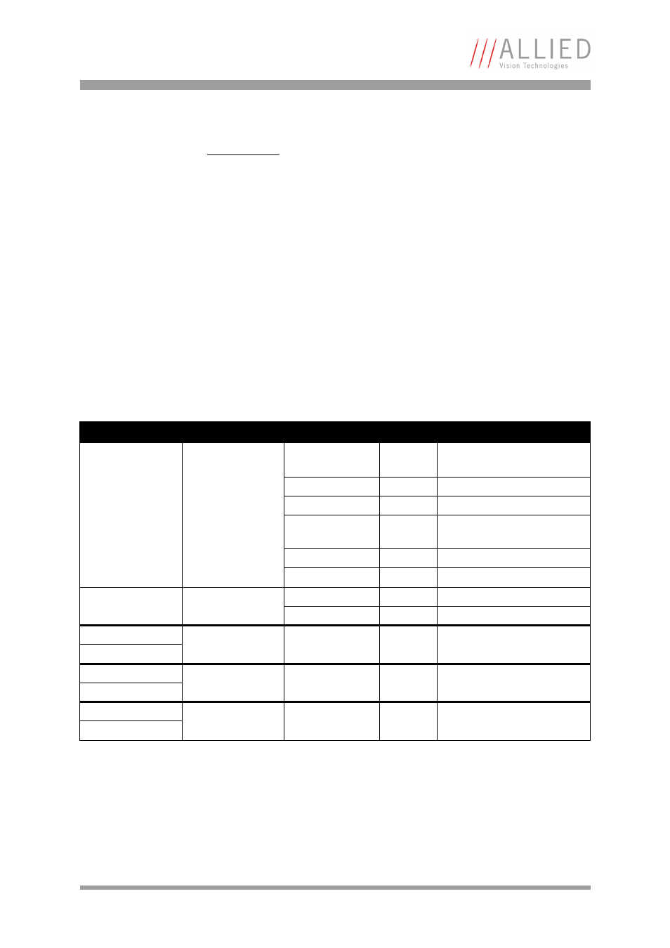
Page 87: Table 31: pwm configura, Tion registers
Camera interfaces
Guppy PRO Technical Manual V4.0.0
85
Pulse-width modulation
The 1 input and 3 outputs are independent. Each output has pulse-width
modulation (PWM) capabilities, which can be used (with additional external
electronics) for motorized speed control or autofocus control.
Period (in µs) and pulse width (in µs) are adjustable via the following regis-
ters (see also examples in Chapter
To enable the PWM feature select output mode 0x09. Control the signal state
via the PulseWidth and Period fields (all times in microseconds (µs)).
Note
•
Note that trigger delay in fact delays the image cap-
ture whereas the IntEna_Delay only delays the leading
edge of the IntEna output signal but does not delay the
image capture.
•
As mentioned before, it is possible to set the outputs
by software. Doing so, the achievable maximum fre-
quency is strongly dependent on individual software
capabilities. As a rule of thumb, the camera itself will
limit the toggle frequency to not more than 700 Hz.
Register
Name
Field
Bit
Description
0xF1000800
IO_OUTP_PWM1
Presence_Inq
[0]
Indicates presence of this
feature (read only)
---
[1]
Reserved
---
[2..3]
Reserved
MinPeriod
[4..19]
Minimum PWM period in µs
(read only)
---
[20..27]
Reserved
---
[28..31]
Reserved
0xF1000804
PulseWidth
[0..15]
PWM pulse width in µs
Period
[16..31]
PWM period in µs
0xF1000808
IO_OUTP_PWM2
Same as
IO_OUTP_PWM1
0xF100080C
0xF1000810
IO_OUTP_PWM3
Same as
IO_OUTP_PWM1
0xF1000814
0xF1000818
IO_OUTP_PWM4
Same as
IO_OUTP_PWM1
0xF100081C
Table 31: PWM configuration registers