Appendix, cont’d, Transient response – Extron Electronics VTG 400D_400 DVI User Guide User Manual
Page 82
Appendix, cont’d
VTG 400D/400 DVI • Appendix
A-18
Phase anomalies of the burst manifest as a wavy appearance at the base of the pulse
region. Transmission line quality and length have more proportional effect on the
higher frequency pulse/burst combinations. Group delay effects may be combated
using a video processing amplifier or an equalizing network at the termination end
of the line.
PAL Multipulse
The 2T pulse is followed by a series of modulated pulses. (1) a 20T pulse
encompassing a 1 MHz sine wave burst, (2) a 12.5T pulse containing a 2 MHz sine
wave burst, (3) a 12.5T pulse containing a 4 MHz sine wave burst, (4) a 12.5T pulse
containing a 4.43 MHz sine wave burst, and (5) a 12.5T pulse containing a 5 MHz
sine wave burst. Much like the multiburst signal discussed earlier, each of these
frequencies provides an intermediate bandwidth point for consideration, including
the color subcarrier and a frequency burst at the bandwidth limit of the system.
The frequency burst inside each pulse is generated to fit within the pulse
symmetrically and have an amplitude which matches the pulse height and duration
without extending past its areal limits. Group delay in a television distribution
system will cause relative time shift between the imposed burst and the
encompassing pulse. Amplitude disturbance of the burst within each pulse
manifests as an upward or downward level shift, which appears as concaved
upward above black level (for low level) to convexed downward beyond black (for
excessive level). Phase anomalies of the burst manifest as a wavy appearance at the
base of the pulse region. Transmission line quality and length will have more of a
proportional effect on the higher frequency pulse/burst combinations. Group delay
effects may be combated using a video processing amplifier or an equalizing
network at the termination end of the line.
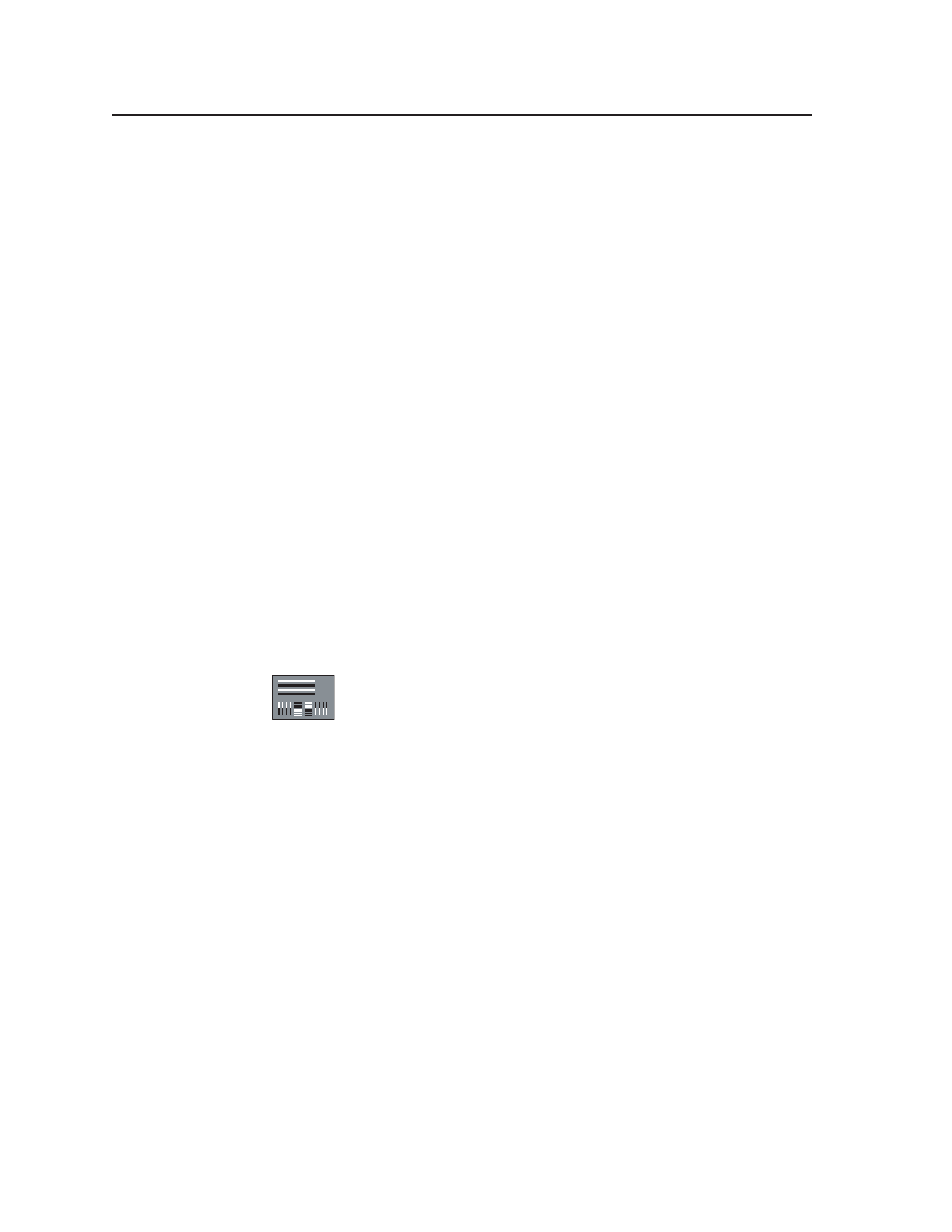
25. Transient Response
This pattern supports analysis of system transient response both from
black to white and white to black. Signal level transitions from the
extremes to middle gray require that the display system response be
carefully designed so that transition artifacts are not visible on the
gray background. Signal overshoot, undershoot, line distortion (streaking), and
ringing (trailing ghosts) manifest on the gray surround region when system
response is less than ideal.
The horizontal white and black bars emphasize lower frequency response issues.
Look for streaks trailing each of the horizontal bars. The short term vertical lines
represent high frequency transitions of time durations which will tend to show up
ringing problems within the high frequency response of the imaging system.
Ringing manifests as dark and light “ghosts” following the vertical lines and bars in
the test pattern.