Symbol definitions – Extron Electronics VTG 400D_400 DVI User Guide User Manual
Page 39
3-3
VTG 400D/400 DVI • Serial Communication
Using the command/response tables
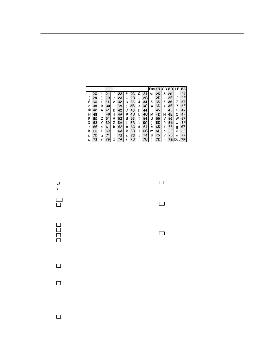
The command/response tables in this chapter list valid command ASCII codes,
the video test generator’s responses to the host, and a description of the
command’s function or the results of executing the command.
The ASCII to HEX conversion table below is for use with the
command/response tables.
ASCII to HEX Conversion Table
•
The command/response tables use symbols (defined below) to represent variables.
Symbol definitions
= CR/LF (carriage return/line feed) (hex 0D 0A)
= CR (carriage return)
•
= Space
Esc
= Escape key
X1
= Controller firmware version (listed to two decimal
places, i.e. x.xx)
?.?? = Invalid firmware / firmware not loaded
x.xx* = Currently active firmware
X2
= Test pattern number ( 1 or 2 digits)
X3
= Scan rate number (1 to 3 digits)
X4
= Scan rate description (32 characters)
X5
= Timeout interval (0 – 4)
0 = Never time out
1 = 5 minutes
2 = 10 minutes
3 = 15 minutes
4 = 30 minutes
X6
= Test pattern auto-sequence interval (1 – 3)
1 = 15 seconds
2 = 30 seconds
3 = 1 minute
X7
= Audio test signal type
1 = Pink noise
2 = White noise
3 = Sine wave
4 = Square wave
5 = Frequency sweep
6 = Polarity test
7 = Sine burst
X8
= Audio level units
1 = dBu
2 = dBV
X9
= Audio level (positive)
Pink noise: N/A
Polarity test: N/A
All other signal types: 0 to +6 dBu
(0 dBV to +4 dBV)
X10
= Audio level (negative)
Pink noise: -72 dBu to -4 dBu
(-74 dBV to -6 dBV)
Polarity test: -72 dBu to -14 dBu
(-74 dBV to -16 dBV)
All other signal types: -72 dBu to 0 dBu
(-74 dBV to 0 dBV)
X11
= Audio level (positive/negative) (status only)
Pink noise: -72 dBu to -4 dBu
(-74 dBV to -6 dBV)
Polarity test: -72 dBu to -14 dBu
(-74 dBV to -16 dBV)
All other signal types: -72 dBu to +6 dBu
(-74 dBV to +4 dBV)