Installation and operation – Extron Electronics VTG 400D_400 DVI User Guide User Manual
Page 14
Installation and Operation
VTG 400D/400 DVI • Installation and Operation
2-4
5
R-Y, Y, B-Y component video output connectors —
Connect a display
device to the three female BNC connectors for component video output:
Component video output
(R-Y, Y, B-Y)
R-Y
Y
B-Y
6
15-pin RGB output connector —
RGBHV, RGBS, RGsB, and RsGsBs are
output through this 15-pin HD connector.
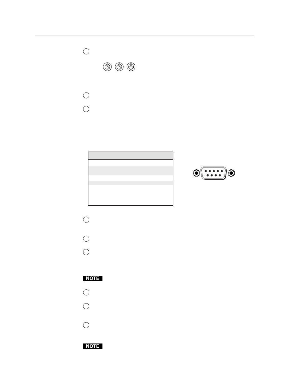
7
RS-232 port —
This 9-pin female D connector provides for two-way RS-232
communication. See chapter three, “Serial Communication”, for
information on how to install and use the control software and SIS
commands.
The default protocol is 9600 baud, 1 stop bit, no parity, and no flow control.
The rear panel RS-232, 9-pin connector has the following pin assignments:
Pin
RS-232 function
Description
1
–
No connection
2
Tx
Transmit data
3
Rx
Receive data
4
–
No connection
5
Gnd
Signal ground
6
–
No connection
7
–
No connection
8
–
No connection
9
–
No connection
DB9 Pin Locations
Female
5
1
9
6
8a
SDI/HDSDI serial digital interface output connector (VTG 400D only) —
Connect an output device to the SDI/HDSDI component output female
BNC.
8b
DVI-I output connector (VTG 400 DVI only) —
Connect an output device
to receive the DVI-D signal from the female DVI-I output connector.
9
Trigger output connector —
Connect an oscilloscope to this female BNC
connector when using an oscilloscope to align its display to a specific point
in the video waveform.
The oscilloscope’s external trigger needs to be configured to accept a TTL
level (0 to 5 V) signal.
10
RCA jack (Audio output 1) —
Unbalanced mono audio is output from this
female jack. See the note below.
11
3.5 mm mini stereo phone jack (Audio output 2) —
Unbalanced mono
audio on both left and right channels is output from this female mini phone
jack. See the note below.
12
XLR audio output connector (Audio output 3) —
Balanced mono audio is
output from this 3-pin male connector.
See
Connecting Audio Outputs later in this chapter for audio wiring
instructions.