Installation and operation, cont’d, Top panel features – Extron Electronics VTG 400D_400 DVI User Guide User Manual
Page 16
Installation and Operation, cont’d
VTG 400D/400 DVI • Installation and Operation
2-6
Top Panel Features
AUDIO
SIGNAL
TYPE
LEVEL
POWER
FREQUENCY
VIDEO
TEST
PATTERN
RANGE
SELECT
RATE
MENU
QUICK
SELECT
SCOPE-TRIGGER
1
2
3
CURSOR
SHAPE
HIDE
4
NEXT
VTG 400
VIDEO & AUDIO TEST GENERATOR
RES: NTSC 720X485
FRQ:15.70kHz 60/30Hz
SIG:Pink noise FRQ:N/A
LEV:-18dBu 97.6mV
Checkerboard 100%
6
7
5
8
1
2
4
3
12
11
9
10
13
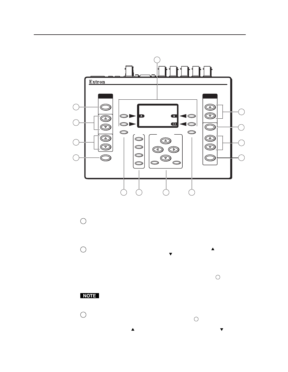
VTG 400D/400 DVI top panel features
1
Audio signal type (Signal Type) —
Press this button to select from among
seven different audio test signals: pink noise, white noise, sine wave,
square wave, frequency sweep, polarity test, and sine burst. The signal type
is indicated on the LCD display. See Selecting audio signals later in this
chapter.
2
Audio output signal level adjustment (Level)
— Press the button to
increase the RMS signal level and the button to decrease the RMS signal
level. See the Audio Setup menu section in this chapter to specify either dBu
or dBV as the signal level unit. The level setting is indicated on the LCD
display.
The audio output level settings for all audio signal types (see
1
above) are
retained after the VTG is powered off. The default setting is -28 dBu for
polarity test and -10 dBu for all other signal types.
If the Level buttons are held down for more than one second, the VTG
automatically advances through the level adjustment in the direction
indicated by the button.
3
Audio frequency adjustment (Frequency) —
When the audio signal type
is either sine wave, square wave, or sine burst (see
1
above), the audio
frequency can be adjusted from 20 Hz to 20 kHz (sine) or 20 Hz to 5 kHz
(square). Press the button to increase the frequency and the button to
decrease the frequency. The adjustment is in 1/12 octave steps. See Setting
the audio frequency
later in this chapter. The audio frequency is indicated on
the LCD display.