Quick start, Installation, Step 1 – Extron Electronics PIP 444 User Guide User Manual
Page 3: Step 2, Step 3, Step 4, 3, 4 step 5, Step 6 (pip 444 only)
QS-1
PIP 422 and PIP 444 Picture-in-Picture Processors • Quick Start
Quick Start — PIP 422 and PIP 444
Installation
Step 1
For tabletop placement, install the four rubber
feet on the bottom of the PIP picture-in-picture
processor. Otherwise, mount the processor in a
rack using the included rack ears or install the
processor in furniture.
Step 2
Turn off power to the input and output devices,
and remove the power cords from them.
Step 3
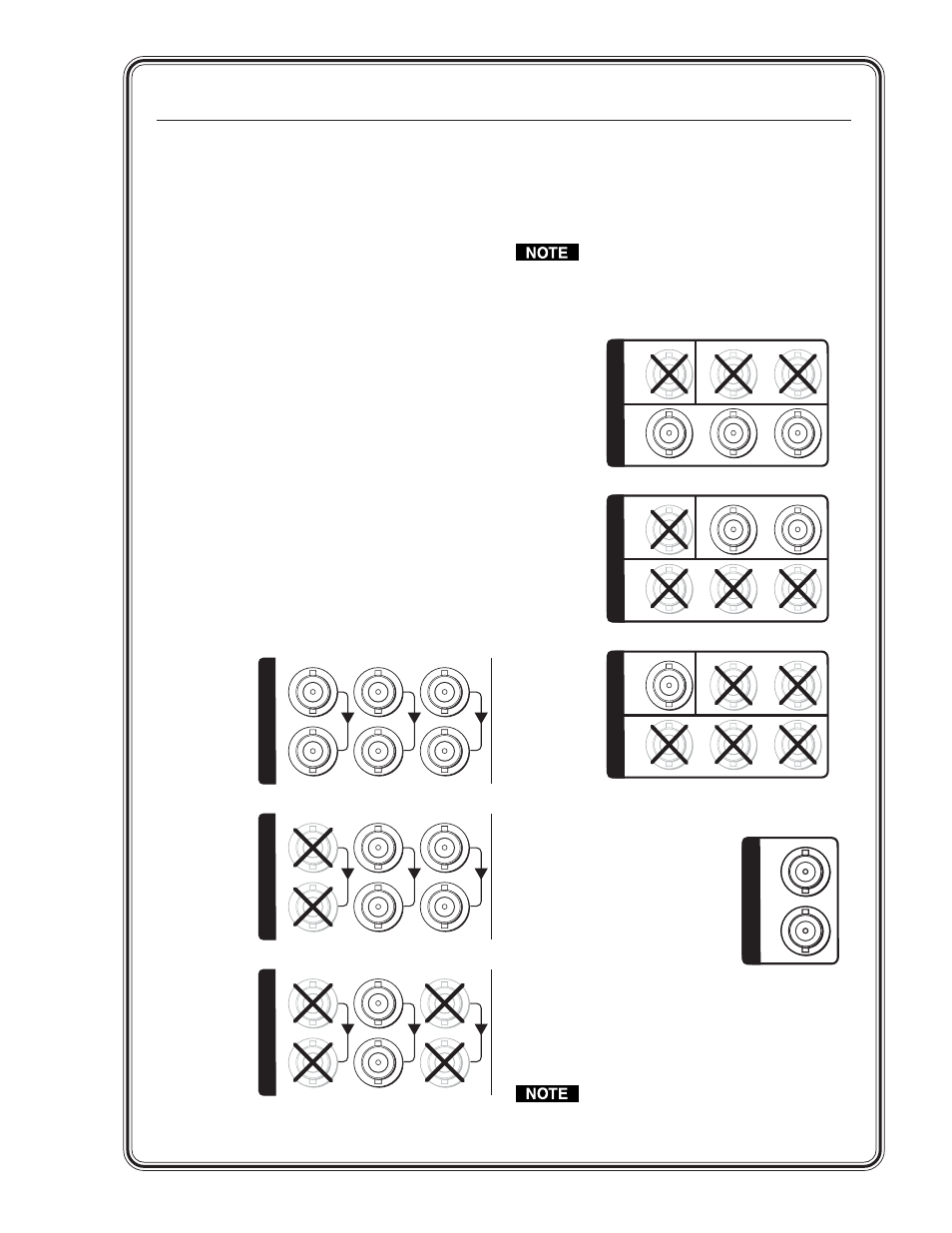
Input connectors —
Connect up to two (PIP 422)
or four (PIP 444) component video, S-video, or
composite video input devices to the top (input)
set of rear panel Inputs BNC connectors (3, 4).
Step 4
Loop-through connectors —
If desired, connect
up to two (PIP 422) or four (PIP 444) component
video, S-video, or composite video display
devices to the bottom (buffered loop-through) set
of rear panel Inputs BNC connectors (3, 4).
R-Y
Component Video
Input
S-Video
Y
/VID
B-Y
/C
1
I
N
P
U
T
S
R-Y
Y
/VID
B-Y/
C
1
Composite Video
I
N
P
U
T
S
R-Y
Y/
VID
B-Y/C
1
I
N
P
U
T
S
Buffered
Loop-through
Input
Buffered
Loop-through
Input
Buffered
Loop-through
3, 4
Step 5
Output connectors —
Connect a component
video, S-video, and/or composite video display
device to the rear panel Output BNC connectors (5).
The component video, S-video, and
composite video outputs are all active
simultaneously, so multiple displays can
be connected.
Step 6 (PIP 444 only)
Genlock connectors —
In(put) connector —
If
desired, connect an external
black burst signal to the rear
panel Genlock Input BNC
connector for genlocking the
video signal in broadcast or
other sync-critical applications (6).
Out(put) connector —
Connect any downstream
equipment that requires genlocking to the rear
panel Genlock Output BNC connector to route
the black burst signal throughout the system in
broadcast or other sync-critical applications.
If no device is connected to the output,
terminate the Genlock output with the
included 75-ohm terminator .
Composite Video
S-Video
Component video
VIDEO
Y
C
R-Y
Y
B-Y
O
U
T
P
U
T
S
VIDEO
Y
C
R-Y
Y
B-Y
O
U
T
P
U
T
S
VIDEO
Y
C
R-Y
Y
B-Y
O
U
T
P
U
T
S
5
6
IN
OUT
G
E
N
L
O
C
K