Installation, cont’d – Extron Electronics PIP 444 User Guide User Manual
Page 14
Installation, cont’d
PIP 422 and PIP 444 Picture-in-Picture Processors • Installation
2-6
3
Input loop-through (bottom) connectors —
If desired, connect local monitors
to these female BNC connectors. The processor buffers the video input and
loops it out on these connectors.
The processor does not alter the video signal between the input and the
buffered loop-through in any way. The processor’s buffered loop-through
output is in the same format as the input.
4
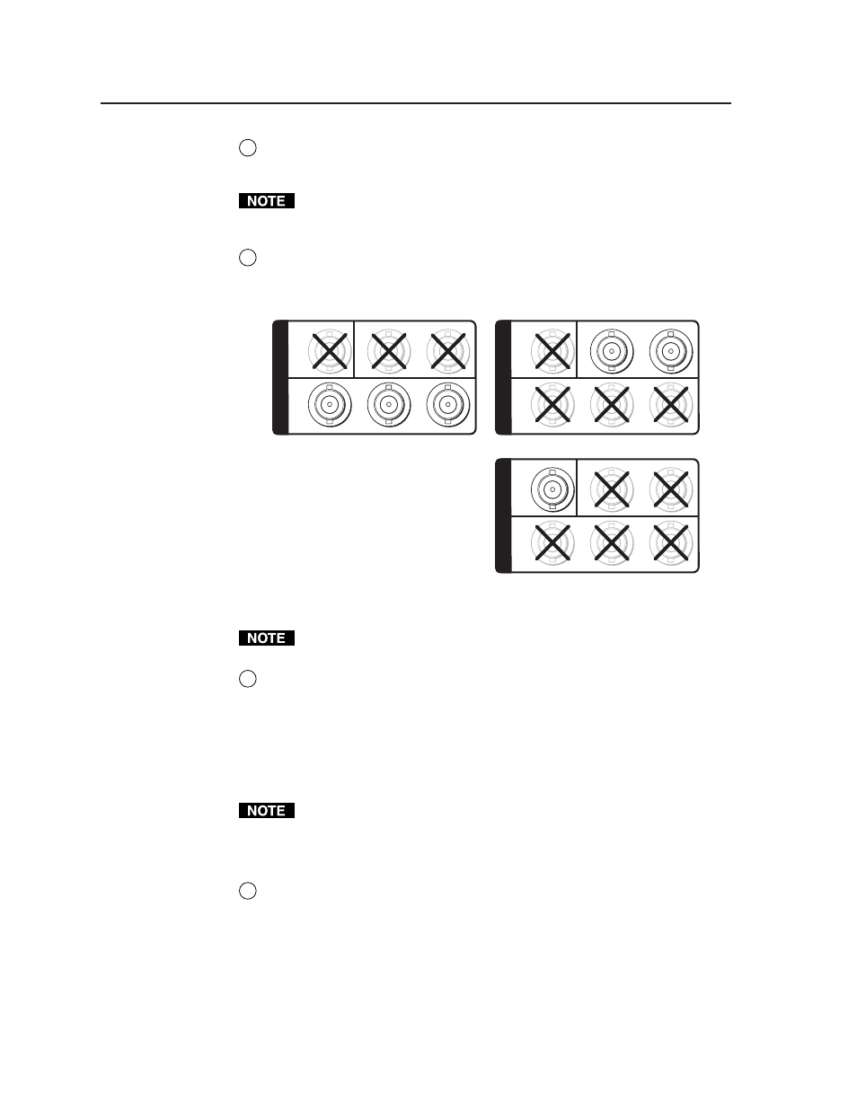
Output connectors —
Connect a component video, S-video, and/or
composite video display device to these BNC connectors. Figure 2-6 shows
how to connect the various video formats.
Composite Video
Component Video
VIDEO
Y
C
R-Y
Y
B-Y
O
U
T
P
U
T
S
S-video
VIDEO
Y
C
R-Y
Y
B-Y
O
U
T
P
U
T
S
VIDEO
Y
C
R-Y
Y
B-Y
O
U
T
P
U
T
S
Figure 2-6 — Video output connections
The component video, S-video, and composite video outputs are all active
simultaneously, so multiple displays can be connected.
5
Genlock connectors (PIP 444 only) —
In(put) connector —
Connect an external black burst signal to this BNC
connector for genlocking the video signal in broadcast or other sync-critical
applications.
Out(put) connector —
Connect any downstream equipment that requires
genlocking to this BNC connector to route the black burst signal throughout
the system in broadcast or other sync-critical applications.
If no device is connected to the output, terminate the Genlock output with the
included 75-ohm terminator .
See “Setting Up Genlock and Vertical Interval Switching”, on the next page,
for detailed Genlock instructions.
6
RS-232/RS-422 connector —
Connect a host computer or control system to
this female 9-pin D connector to allow remote control of the PIP using
Extron’s Simple Instruction Set
™
(SIS
™
) or control software for Windows
®
.
(See Chapter 4, “Remote Control”, for more information.)