Rear panel connections – Extron Electronics PIP 444 User Guide User Manual
Page 13
2-5
PIP 422 and PIP 444 Picture-in-Picture Processors • Installation
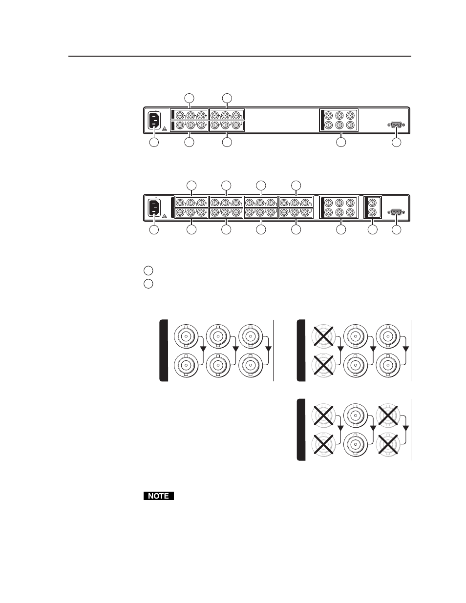
Rear Panel Connections
50/60 Hz
100-240V 0.3A
RS-232/422
VIDEO
Y
C
R-Y
Y/VID
B-Y/C
1
R-Y
V
B-Y
I
N
P
U
T
S
O
U
T
P
U
T
S
R-Y
Y/VID
B-Y/C
2
1
6
4
3
2
3
2
Figure 2-3 — PIP 422 rear panel
50/60 Hz
100-240V 0.3A
RS-232/422
VIDEO
Y
C
R-Y
Y/VID
B-Y/C
1
R-Y
Y
B-Y
I
N
P
U
T
S
O
U
T
P
U
T
S
IN
OUT
G
E
N
L
O
C
K
R-Y
Y/VID
B-Y/C
2
R-Y
Y/VID
B-Y/C
3
R-Y
Y/VID
B-Y/C
4
3
1
6
2
5
4
3
2
3
2
3
2
Figure 2-4 — PIP 444 rear panel
1
Power connector —
Plug the provided IEC power cord into this connector.
2
Input (top) connectors —
Connect up to two (PIP 422) or four (PIP 444)
component video, S-video, or composite video input devices to these BNC
connectors. Figure 2-5 shows how to connect the various video formats.
R-Y
Component Video
Input
S-Video
Y
/VID
B-Y
/C
1
I
N
P
U
T
S
R-Y
Y
/VID
B-Y/
C
1
Composite Video
I
N
P
U
T
S
R-Y
Y/
VID
B-Y/C
1
I
N
P
U
T
S
Buffered
Loop-through
Input
Buffered
Loop-through
Figure 2-5 — Video input and buffered loop-through connections
Connect only one video format to each input.
You must configure each input to identify the connected video format. See
chapter 3, “Operation”.