Table or wall mounting – Extron Electronics PIP 444 User Guide User Manual
Page 11
2-3
PIP 422 and PIP 444 Picture-in-Picture Processors • Installation
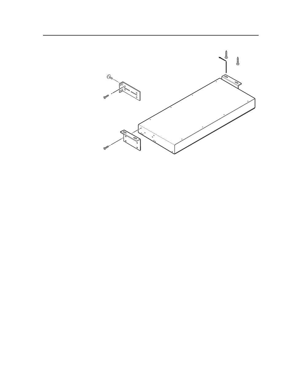
#8 Screw
(4 Plcs)
Each Side
Optional Furniture Mounting Bracket
Supplied Rack Mounting Bracket
Mounting Screws
(2 Plcs)
Each Side
or
Figure 2-1 — Mounting a PIP
3
.
Insert the processor into the rack, align the holes in the mounting bracket with
those of the rack.
4
.
Secure the processor to the rack using the supplied machine screws.
Table or wall mounting
The table/wall mounting brackets extend approximately 1/4" (6.4 mm) above the
top surface of the processor enclosure. This design allows for an air space between
the enclosure and the surface to which it is mounted. Table or wall mount the
PIP as follows:
1
.
Remove the feet from the underside of the PIP, if installed.
2
.
Attach the table/wall mounting brackets to the processor with the eight
provided #8 machine screws (figure 2-1).
3
.
Hold the processor with the attached brackets against the underside of the
table or other furniture, or against the wall. Mark the location of the screw
holes of the bracket on the mounting surface.
4
.
Drill 3/32" (2 mm) diameter pilot holes, 1/4" (6.4 mm) deep in the mounting
surface at the marked screw locations.
5
.
Insert #8 wood screws into the four pilot holes. Tighten each screw into the
mounting surface until just less than 1/4" (6 mm) of the screw’s head
protrudes.
6
.
Align the mounting screws with the slots in the brackets and place the
processor against the surface, with the screws through the bracket slots.
7
.
Slide the PIP slightly forward or back, then tighten all four screws to secure
the processor in place.