Rear panel power indicators, Front panel operations – Extron Electronics Fiber Matrix 6400 User Manual
Page 33
3-7
Fiber Matrix 6400 Switcher • Operation
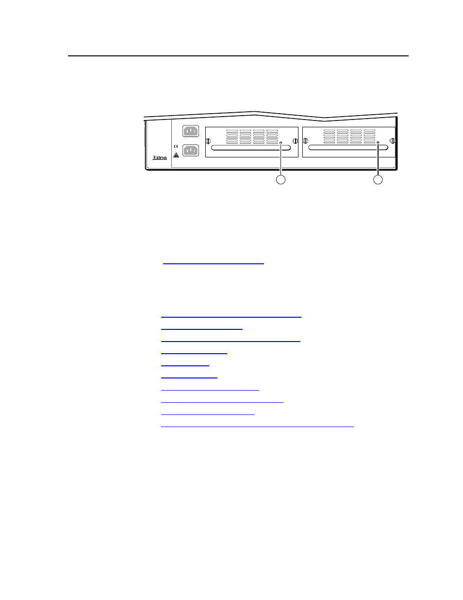
Rear Panel Power Indicators
The two power supply modules (primary power supply and redundant power
supply, figure 3-3) each have a 2-color LED.
ANAHEIM, CA
100-240V 50/60Hz
2A MAX.
100-240V 50/60Hz
2A MAX.
REDUNDANT
PRIMARY
PRIMARY POWER SUPPLY
REDUNDANT POWER SUPPLY
1
1
Figure 3-3 — Rear panel power supply indicators
a
Primary and Redundant Power Supply LEDs —
Green —
Indicates that the associated power supply is operating within
normal tolerances.
Red —
Indicates that the associated power supply has failed. See chapter 7,
“Maintenance and Modifications”, to replace the power supply.
Front Panel Operations
The following paragraphs detail the power-up process and then provide sample
procedures for the following actions:
• Creating ties, sets of ties, and configurations
• Changing a configuration
• Viewing ties, sets of ties, and configurations
• Creating I/O groups
• Saving a preset
• Recalling a preset
• Muting and unmuting outputs
• Locking and unlocking the front panel
• Performing front panel resets
• Reading and setting the RS-232/RS-422 Remote port settings