Rj-45 connector wiring, Remote port, Rj-45 connector wiring -7 – Extron Electronics Fiber Matrix 6400 User Manual
Page 23: Remote port -7
2-7
Fiber Matrix 6400 Switcher • Installation
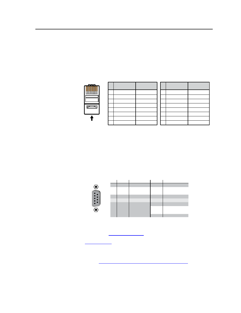
RJ-45 connector wiring
The Ethernet cable can be terminated as a straight-through cable or a crossover
cable and must be properly terminated for your application (figure 2-4).
•
Crossover cable — Direct connection between the computer and the Fiber
Matrix switcher
•
Patch (straight) cable — Connection of the Fiber Matrix switcher to an
Ethernet LAN
A cable that is wired as T568A at one end
and T568B at the other (Tx and Rx pairs
reversed) is a "crossover" cable.
A cable wired the same at both ends is
called a "straight-through" cable, because
no pin/pair assignments are swapped.
12345678
RJ-45
Connector
Insert Twisted
Pair Wires
Pins:
Crossover Cable
Straight-through Cable
Pin
1
2
3
4
5
6
7
8
Wire color
White-green
Green
White-orange
Blue
White-blue
Orange
White-brown
Brown
Wire color
T568A
T568B
End 1
End 2
End 1
End 2
White-orange
Orange
White-green
Blue
White-blue
Green
White-brown
Brown
Pin
1
2
3
4
5
6
7
8
Wire color
White-orange
White-green
Blue
White-blue
White-brown
Brown
Wire color
T568B
T568B
White-orange
Orange
Orange
White-green
Blue
White-blue
Green
Green
White-brown
Brown
Figure 2-4 — RJ-45 connector and pinout tables
Remote port
e
Remote RS-232/RS-422 connector — Connect a host device, such as a
computer, touch panel control, or RS-232 capable PDA to the switcher via this
9-pin D connector for serial RS-232/RS-422 control (figure 2-5).
RS-232 Function
Pin
Function
1
2
3
4
5
6
7
8
9
—
TX
RX
—
Gnd
—
—
—
—
Not used
Transmit data
Receive data
Not used
Signal ground
Not used
Not used
Not used
Not used
—
TX–
RX–
—
Gnd
—
RX+
TX+
—
Not used
Transmit data (–)
Receive data (–)
Not used
Signal ground
Not used
Receive data (+)
Transmit data (+)
Not used
RS-422
5
1
9
6
RS232/RS422
REMO
TE
Figure 2-5 — Remote RS-232/RS-422 connector
See chapter 4, “Programmer’s Guide”, for definitions of the SIS commands
(serial commands to control the switcher via this connector) and chapter 5,
“Matrix Software”, for details on how to install and use the control/
configuration software.
N
The switcher can support either the RS-232 or RS-422 serial communication
protocol, and can operate at 9600, 19200, 38400, or 115200 baud rates.
See “Selecting the rear panel Remote port protocol and baud rate” on page 3-27,
to configure the RS-232/RS-422 port from the front panel.
If desired, connect an MKP 2000 or MKP 3000 remote control panel to the
switcher’s RS-232/RS-422 connector. Refer to the MKP 2000 Remote Control
Panel User’s Manual
or the MKP 3000 User’s Manual for details.