Removing the i/o board or blank panel, Removing the i/o board or blank panel -3, Out in – Extron Electronics Fiber Matrix 6400 User Manual
Page 123: Figure 7-2 — i/o board replacement
7-3
Fiber Matrix 6400 Switcher • Maintenance and Modifications
On the fiber optic I/O boards, locations A through H correspond to the transceiver
modules, each of which includes an input and an output. Therefore, locations A
through H are numbered from left to right.
On the SDI/HD-SDI I/O boards, inputs and outputs are grouped separately, with
inputs A through H on the left and outputs A through H on the right.
Removing the I/O board or blank panel
Remove an I/O board or blank panel as follows:
N
The I/O boards are hot-swappable. You do not need to power down the switcher
to remove an I/O board.
1
.
For an I/O board
, disconnect any connected cables.
2
.
Rotate the left and right knurled knobs to completely loosen the captive
screws.
3
.
Gently pull on the knurled knobs/captive screws to loosen the board or panel
from the backplane.
4
.
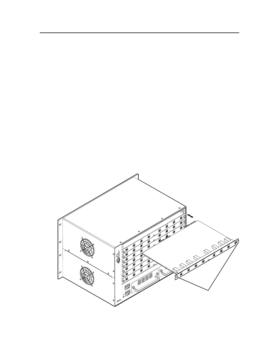
Slide the board or panel out of the chassis (figure 7-2).
C
Do not touch the electronic components or the connectors on the backplane
or on the circuit boards without being electrically grounded. Handle
circuit boards by their edges only. ESD can damage circuits, even if you
cannot feel, see, or hear it.
5
.
Place the removed board on an anti-static surface or in an anti-static container.
100-240V 50/60H
z
1.2A MAX.
100-240V 50/60H
z
1.2A MAX.
REDUND
ANT
PRIMAR
Y
1 - 8
9 - 16
17 - 24
25 - 32
33 - 40
41 - 48
49 - 56
57 - 64
LAN
ACT
LINK
RESET
ANAHEIM
, CA
PRIMAR
Y PO
WER SUPPL
Y
REDUND
ANT PO
WER SUPPL
Y
Align with Plastic Guides
Knurled Knobs
OUT
IN
A
OUT
IN
B
OUT
IN
C
OUT
IN
D
OUT
IN
E
OUT
IN
F
OUT
IN
G
OUT
IN
H
OUT
IN
A
OUT
IN
B
OUT
IN
C
OUT
IN
D
OUT
IN
E
OUT
IN
F
OUT
IN
G
OUT
IN
H
OUT
IN
A
OUT
IN
B
OUT
IN
C
OUT
IN
D
OUT
IN
E
OUT
IN
F
OUT
IN
G
OUT
IN
H
OUT
IN
A
OUT
IN
B
OUT
IN
C
OUT
IN
D
OUT
IN
E
OUT
IN
F
OUT
IN
G
OUT
IN
H
OUT
IN
A
OUT
IN
B
OUT
IN
C
OUT
IN
D
OUT
IN
E
OUT
IN
F
OUT
IN
G
OUT
IN
H
OUT
IN
A
OUT
IN
B
OUT
IN
C
OUT
IN
D
OUT
IN
E
OUT
IN
F
OUT
IN
G
OUT
IN
H
OUT
IN
A
OUT
IN
B
OUT
IN
C
OUT
IN
D
OUT
IN
E
OUT
IN
F
OUT
IN
G
OUT
IN
H
IN
OUT
IN
A
OUT
IN
B
OUT
IN
C
OUT
IN
D
OUT
IN
E
OUT
IN
F
OUT
IN
G
OUT
IN
H
Figure 7-2 — I/O board replacement