Matrix software, cont’d – Extron Electronics Fiber Matrix 6400 User Manual
Page 104
Matrix Software, cont’d
Fiber Matrix 6400 Switcher • Matrix Software
5-20
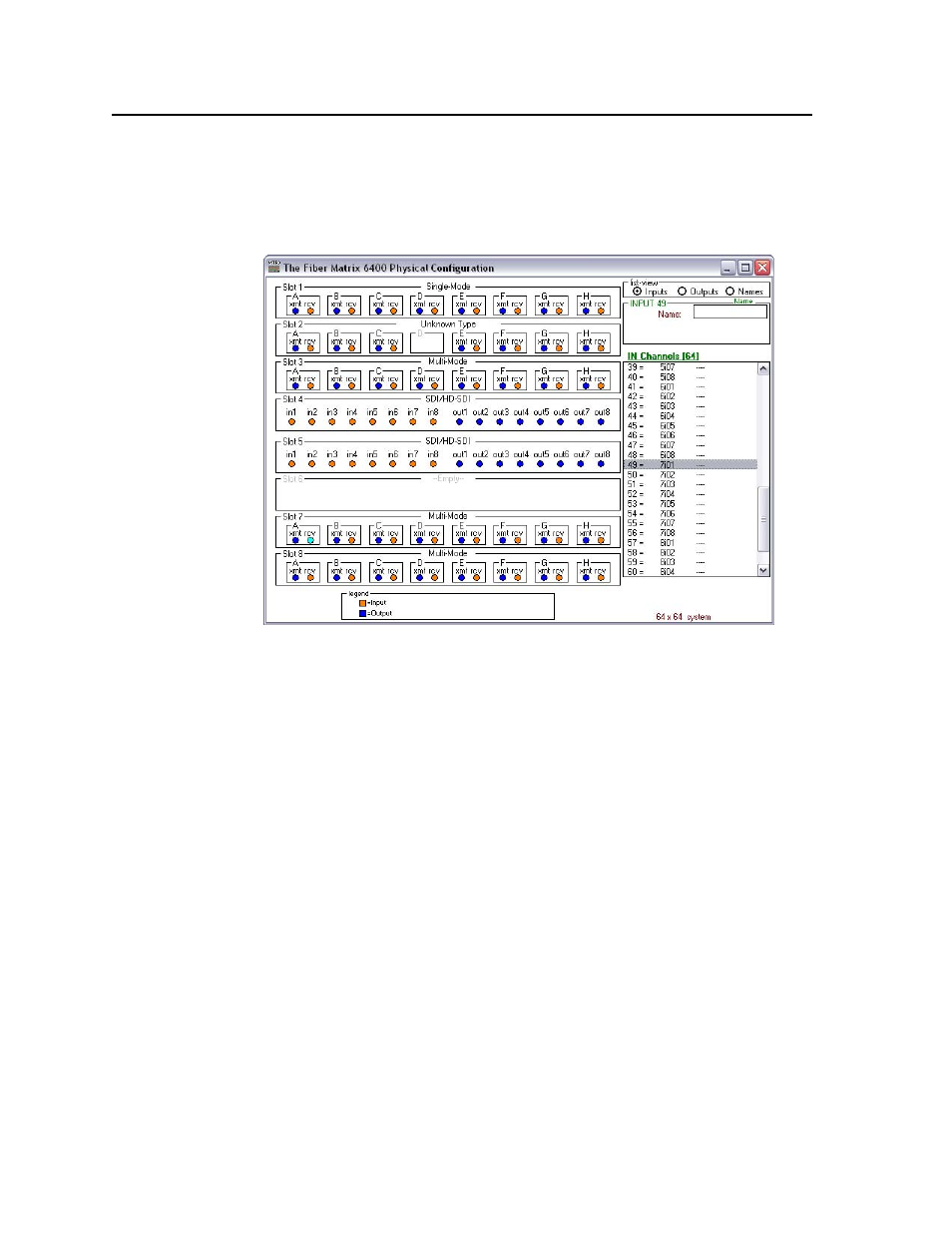
Physical Switcher Layout —
Opens the Fiber Matrix 6400 Physical Configuration
window (figure 5-15), which displays the I/O board type installed in each slot.
The Channels field can be helpful in identifying a specific input or output. In
figure 5-15, for example, input 49 is identified as slot 7, input transceiver 1
(7i01).
Figure 5-15 — Physical Configuration window
Name presets —
Allows you to assign a name to each of the 64 memory presets.
N
Preset names are limited to 12 upper- and lower-case alphanumeric characters,
space, and the _ and / characters.
The following characters are invalid in preset names:
+ ~ , @ = ‘ [ ] { } < > ’ “ ; : | \ and ?.
Show RS-232 Strings —
Displays the ASCII commands that are used by the current
configuration. You can refer to these for SIS programming.
I/O group settings —
Allows you to establish I/O groups.
Room configuration —
Allows you to assign outputs to rooms or delete outputs
from rooms.
N
A Room is a subset of outputs that are logically related to each other, as
determined by the operator. The Fiber Matrix switcher supports up to 10 rooms,
each of which can consist of from 1 to 16 outputs.
Initialize
—
Initializes and clears any or all of the following: ties, presets, preset
names, icon names, and icons.