GE Industrial Solutions Millennium II Controller J85501P-1 User Manual
Page 98
Basic Installation and User’s Guide for the Millennium II Controller
Issue 3 January 2008
98
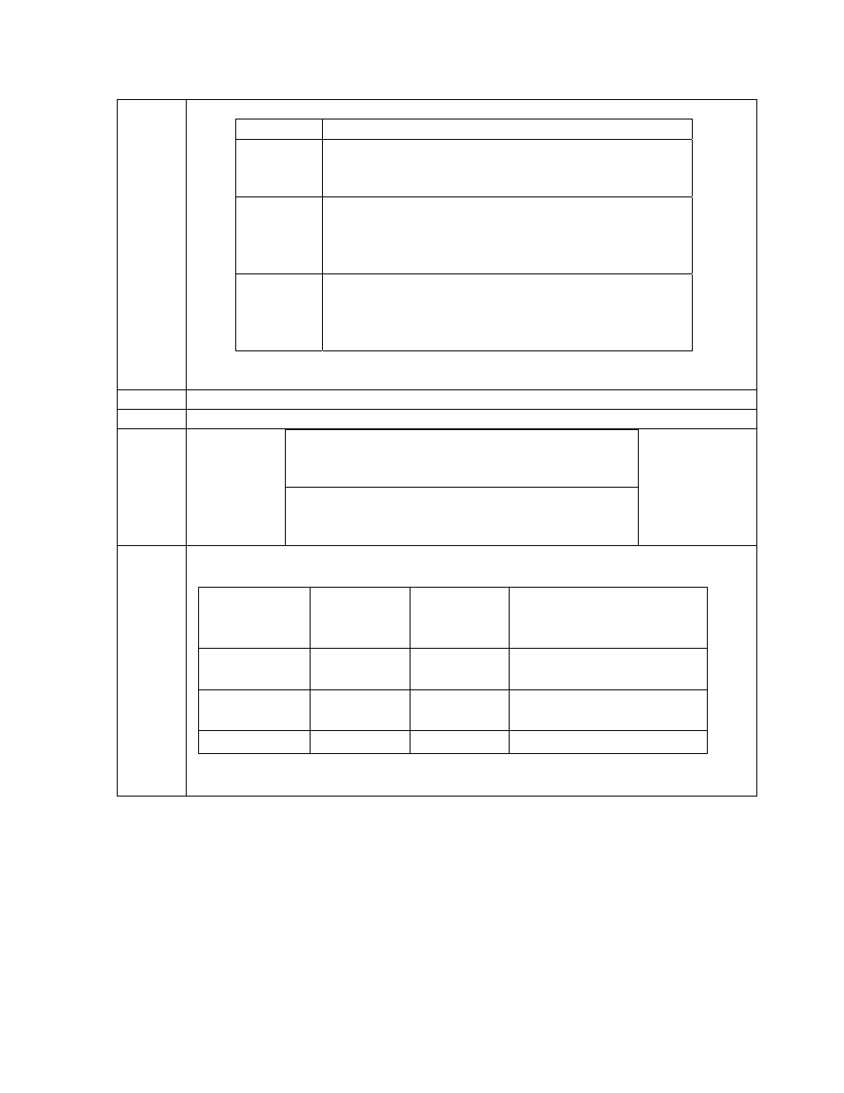
8.
Connect Alarm Wiring
Step Action
a.
On the controller, locate the BSL alarm block. It is
located in the upper right hand corner of the MCR1
board. (see Figure 6-11)
NOTE:
It is very important, in the next step, to follow the
Alarm Input/Output table in this manual when
connecting the alarms. Some Pins may have
changed their function.
b.
Route the alarm wires through the open holes above
the alarm block and terminate them accordingly. You
may need to reference the Millennium II Alarm
Input/Output section for proper connections.
9.
Connect RPM Bus Wire
Action
If NO cable terminated on TB200 on the
Millennium, then proceed to the next item for
connection.
If a cable terminated on TB200 on the
Millennium, connect the old bus cable to TB1 on
the Millennium II. (see Figure 6-11)
NOTE: Wrap the cable through the EMI inductor bead twice. Place the bead
approximately 3 inches from the end of the cable, closest to the controller.
TB- 1 Pin
Assignments
TB-1 Pin
Descriptions
RPM
Conductor
Color
RPM Conductor
Description
6 *6
Blue
or
White
Power/Communications
8 *8
Blue
or
White
Power/Communications
9 or 10
FGND
Bare wire
Shield
*connections of the bus wire are NOT polarity sensitive.