14 class id 28 motor data object, 16 class id 29h control supervisory object – GE Industrial Solutions AF-650 GP DeviceNet User Manual
Page 34
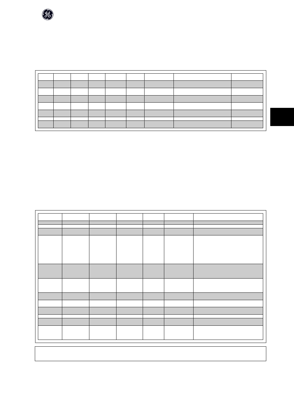
5.3.14 Class ID 28 Motor Data Object
In this object, the current motor data can be configured and read out. The Instances, attributes and services supported for this class are listed below.
5.3.15 Class ID 0/28 Motor Data Object
Attribute
Access
Name
Data type
Generic maxi-
mum values
Units
Default
Description
Parameter
reference
3
Get/set
Motor type
USINT
7
7
7 = Squirrel Cage Induction Motor
par. P-20 Motor Con-
struction
6
Get/set
Rated cur-
rent
UNIT
0-100.00
100mA
Drive dependent
Stator Current rating (from motor nameplate) par. P-03 Motor Current
7
Get/set
Rated volt-
age
UNIT
200-500
volt
Drive dependent
Base Voltage rating (from motor nameplate)
par. F-05 Motor Rated
Voltage
8
Get/set
Rated pow-
er
UDINT
0-18500
Watt
Drive dependent
Power rating at rated frequency (from motor
nameplate)
par. P-07 Motor Power
[kW]
9
Get/set
Rated fre-
quency
UNIT
1-1000
Hz
Drive dependent
Elec. frequency rating (from motor name-
plate)
par. F-04 Base Frequen-
cy
12
Get/set
Pole count
UINT
Drive dependent
Number of poles in the motor
par. P-01 Motor Poles
15
Get/set
Base speed UNIT
100-60000
RPM
Drive dependent
Nominal motor speed (from motor name-
plate)
par. P-06 Base Speed
* only on AF-650 GP drive
5.3.16 Class ID 29h Control Supervisory Object
The Control Supervisory Object can be used for process control and monitoring of the frequency converter, as an alternative to the I/O Instances defined in the
section “How to control the Frequency Converter”.
The attributes supported for this class are listed below.
5.3.17 Class ID 0x29
Attribute
Access
Name
Data type
Min/
Max
Default
Description
3
Get/Set
Run 1
Bool
0-1
Run Fwd, see note below
4
Get/Set
Run 2
Bool
0-1
Run rev, see note below
5
Get/Set
NetCtrl
Bool
0-1
1
0 = Local Control
1 = Control from Network
6
Get
State
USINT
0-7
0 = Vendor specific
1 = Start up
2 = Not ready
3 = Ready
4 = Enabled
5 = Stopping
6 = Fault stop
7 = Fault
7
Get
Running 1
Bool
0-1
0
0 = Other state
1 = (Enable and Run 1)
or (Stopping and Running 1)
or (Fault Stop and Running 1)
8
Get
Running 2
Bool
0-1
0
0 = Other state
1 = (Enable and Run 2)
or (Stopping and Running 2)
or (Fault Stop and Running 2)
9
Get
Ready
Bool
0-1
0 = Other state
1 = Ready or Enabled or Stopping
10
Get
Fault
Bool
0-1
0
0 = No Faults Present
1 = Fault Occured (latched)
12
Get/Set
Fault Rst
Bool
0-1
0 = No Action
1 ->1 = Reset Fault
13
Get
Fault Code
UINT
15
Get
Ctrl From Net
Bool
0-1
1
0 = Control is local
1 = Control is from Network
16
Get/Set
DN Fault Mode
UINT
0-2
1
Action on loss of DeviceNet
0 = Fault + Stop
1 = Ignore (Warning Optional)
2 = Drive specific
NB!
The ODVA drive profile selected in par. P-20 Motor Construction is available only when Instances 20/70 or 21/71 are selected.
AF-600FP /650 GP DeviceNet Operating Instructions
33
5