5 ge drive control profile – GE Industrial Solutions AF-650 GP DeviceNet User Manual
Page 21
Example:
par. P-06 Base Speed = 1420 RPM
par. F-04 Base Frequency = 50 Hz
par. F-53 Maximum Reference = 1420 RPM
In order to run the motor at 25%, the reference transmitted must be: (1420*0,25) = 355 = 163hex
163hex => 25% => Fout = 12,5Hz
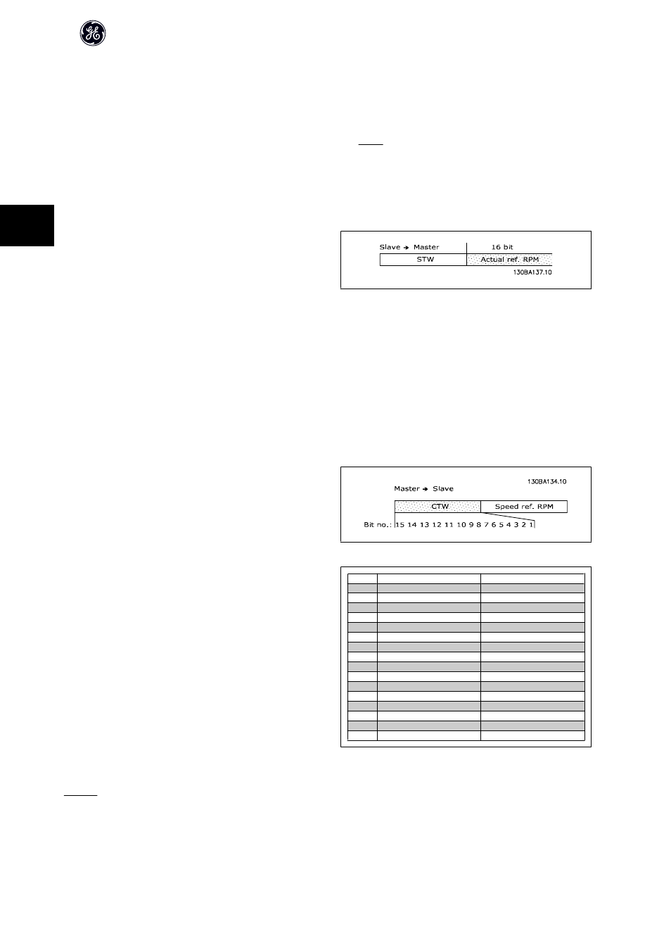
4.4.4 Actual Output Speed under Instances 20/70 and 21/71
The value of the actual speed of the motor is transmitted in the form of a 16-bit word. The value is transmitted as a whole number. Negative figures are formed
by means of 2s complement.
The actual speed value has the following format:
-32767 (8000 Hex) [RPM] -> +32767 [RPM] (7FFF Hex) [RPM]
4.5 GE Drive Control Profile
4.5.1 Control Word under Instances 100/150, 101/151 and 102/152
To select GE drive protocol in the control word, par. O-10 Control Word Pro-
file must be set to Drive protocol [0]. The control word is used to send
commands from a master (PLC or PC) to a slave (frequency converter).
The control words in Instances 100/101/102 are defined as follows to the
right:
Bit
Bit value = 0
Bit value = 1
00
Reference value
External selection lsb
01
Reference value
External selection msb
02
DC brake
Ramp
03
Coasting
No coasting
04
Quick stop
Ramp
05
Hold output frequency
Use ramp
06
Ramp stop
Start
07
No function
Reset
08
No function
Jog
09
Ramp 1
Ramp 2
10
Data invalid
Data valid
11
No function
Relay 01 active
12
No function
Relay 04 active
13
Parameter set-up
Selection lsb
14
Parameter set-up
Selection msb
15
No function
Reverse
Explanation of the Control Bits:
Bits 00/01
Bits 00 and 01 are used to choose between the four reference values, which are pre-programmed in par. C-05 Multi-step Frequency 1 - 8 according to the table
to the right:
AF-600FP /650 GP DeviceNet Operating Instructions
20
4