GE Industrial Solutions AF-650 GP DeviceNet User Manual
Page 22
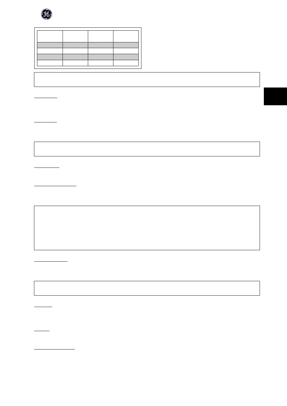
Programmed
ref. value
Parameter
Bit 01
Bit 00
1
C-05 [0]
0
0
2
C-05 [1]
0
1
3
C-05 [2]
1
0
4
C-05 [3]
1
1
NB!
In par. O-56 Preset Reference Select a selection is made to define how Bit 00/01 gates with the corresponding function on the digital inputs.
Bit 02, DC brake:
Bit 02 = 0 leads to DC braking and stop. Braking current and duration are set in par. B-01 DC Brake Current and par. B-02 DC Braking Time .
Bit 02 = 1 leads to ramping.
Bit 03, Coasting:
Bit 03 = 0 causes the frequency converter to immediately "let go" of the motor (the output transistors are "shut off"), so that it coasts to a standstill.
Bit 03 = 1 enables the frequency converter to start the motor if the other starting conditions have been fulfilled.
NB!
In par. O-50 Coasting Select a selection is made to define how Bit 03 gates with the corresponding function on a digital input.
Bit 04, Quick stop:
Bit 04 = 0 causes a stop, in which the motor speed is decelerated to stop via par. C-23 Quick Stop Decel Time.
Bit 05, Hold output frequency:
Bit 05 = 0 causes the present output frequency (in Hz) to freeze. The frozen output frequency can then be changed only by means of the digital inputs (par.
E-01 Terminal 18 Digital Input to par. E-06 Terminal 33 Digital Input) programmed to Speed up and Speed down.
NB!
If Hold output is active, only the following can stop the frequency converter:
•
Bit 03 Coasting stop
•
Bit 02 DC braking
•
Digital input (par. E-01 Terminal 18 Digital Input to par. E-06 Terminal 33 Digital Input) programmed to DC braking, Coasting stop or Reset and coasting
stop.
Bit 06, Ramp stop/start:
Bit 06 = 0 causes a stop, in which the motor speed is decelerated to stop via the selected ramp down parameter.
Bit 06 = 1 permits the frequency converter to start the motor, if the other starting conditions have been fulfilled.
NB!
In par. O-53 Start Select a selection is made to define how Bit 06 Ramp stop/start gates with the corresponding function on a digital input.
Bit 07, Reset:
Bit 07 = 0 does not cause a reset.
Bit 07 = 1 causes the reset of a trip. Reset is activated on the leading edge of the signal, i.e. when changing from logic 0 to logic 1.
Bit 08, Jog:
Bit 08 = 1 causes the output frequency to be determined by par. C-21 Jog Speed [RPM].
Bit 09, Selection of ramp 1/2:
Bit 09 = "0" means that ramp 1 is active (par. H-07 Accel/Decel Time 1 Type to par. SP-73 Decel Time 1 S-ramp Ratio at Decel. Start).
AF-600FP /650 GP DeviceNet Operating Instructions
21
4