GE Industrial Solutions AF-650 GP DeviceNet User Manual
Page 24
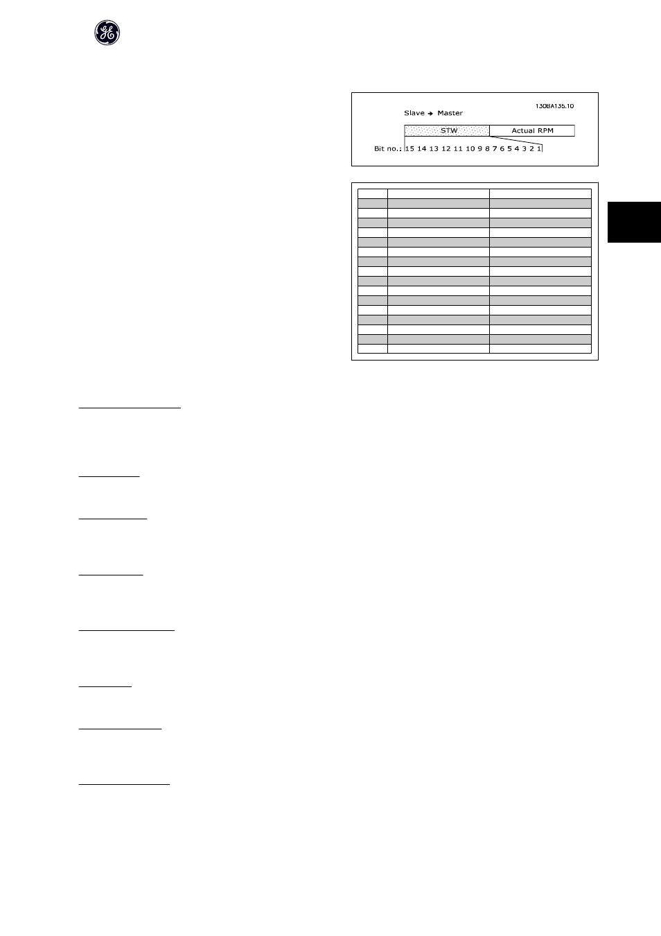
4.5.2 Status Word under Instances 100/150, 101/151 and 102/152
The status words in Instances 150/151/152 are defined as follows to the right:
Bit
Bit = 0
Bit = 1
00
Control not ready
Control ready
01
Drive not ready
Drive ready
02
Coasting
Enable
03
No error
Trip
04
No error
Error (no trip)
05
Reserved
-
06
No error
Trip lock
07
No warning
Warning
08
Speed reference
Speed = reference
09
Local operation
Bus control
10
Out of frequency limit
Frequency limit ok
11
No operation
In operation
12
Drive ok
Stopped, auto start
13
Voltage ok
Voltage exceeded
14
Torque ok
Torque exceeded
15
Timer ok
Timer exceeded
Explanation of the Status Bits:
Bit 00, Control not ready/ready:
Bit 00 = 0 means that the frequency converter has tripped.
Bit 00 = 1 means that the frequency converter controls are ready, but that the power component is not necessarily receiving any power supply (in case of external
24 V supply to controls).
Bit 01, Drive ready:
Bit 01 = 1. The frequency converter is ready for operation.
Bit 02, Coasting stop:
Bit 02 = 0. The frequency converter has released the motor.
Bit 02 = 1. The frequency converter can start the motor when a start command is given.
Bit 03, No error/trip:
Bit 03 = 0 means that the frequency converter is not in fault mode.
Bit 03 = 1 means that the frequency converter is tripped, and that a reset signal is required to re-establish operation.
Bit 04, No error/error (no trip):
Bit 04 = 0 means that the frequency converter is not in fault mode.
Bit 04 = 1 means that there is a frequency converter error but no trip.
Bit 05, Not used:
Bit 05 is not used in the status word.
Bit 06, No error / trip lock:
Bit 06 = 0 means that the frequency converter is not in fault mode.
Bit 06 = 1 means that the frequency converter is tripped, and locked.
Bit 07, No warning/warning:
Bit 07 = 0 means that there are no warnings.
Bit 07 = 1 means that a warning has occurred.
AF-600FP /650 GP DeviceNet Operating Instructions
23
4