3 e.g.: status word network using ppo type – GE Industrial Solutions AF-600 FP Profibus DP User Manual
Page 71
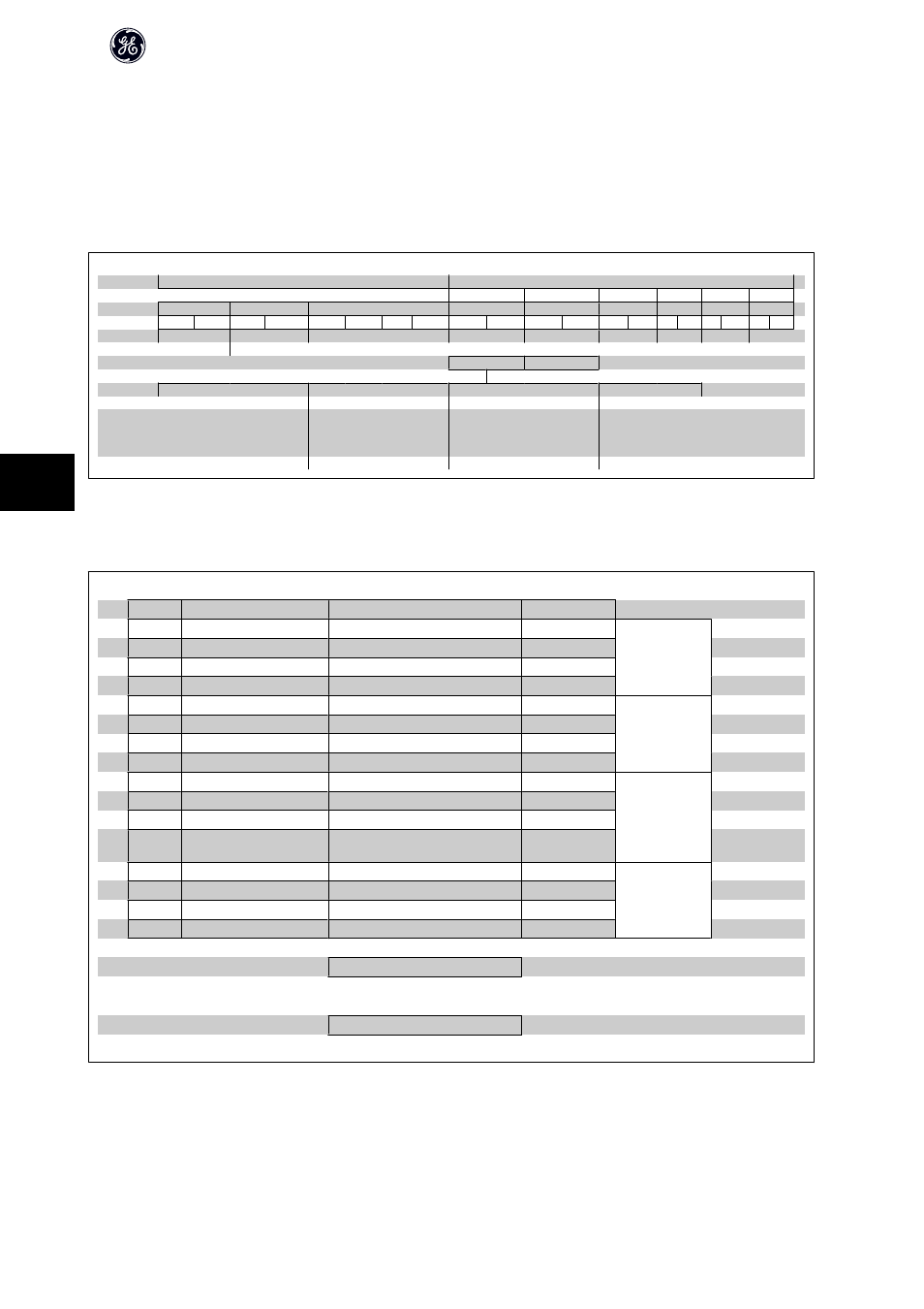
7.3 E.g.: Status Word Network using PPO Type
This example shows how the control word network relates to the PLC and the frequency converter, using GE Drive Control Profile.
The control word network is sent from the PLC to the frequency converter. PPO Type 3 is used in the example in order to demonstrate the full range of modules.
All the values shown are arbitrary, and are provided for the purposes of demonstration only.
PCV
PCD
1
2
3
4
5
6
PCA
IND
PVA
CTW
MRV
PCD
PCD
PCD
PCD
0F
07
20
00
PIW:
256
258
260
262
264
266
268
270
272
274
master slave
STW
MAV
Bit no.:
15
14
13
12
11
10
9
8
7
6
5
4
3
2
1
0
0
0
0
0
0
1
0
0
0
1
1
1
1
1
0
0
0
4
7
C
The table above indicates the bits contained within the statusword, and how they are presented as process data in PPO type 3 for this example.
The following table indicates which bit functions, and which corresponding bit values are active for this example.
Bit
Bit value = 0
Bit value = 1
Bit value
00
Control not ready
Control ready
1
7
01
Drive not ready
Drive ready
1
02
Coasting
Enable
1
03
No error
Trip
0
04
No error
Error (no trip)
0
0
05
Reserved
-
0
06
No error
Triplock
0
07
No warning
Warning
0
08
Speed reference
Speed = reference
1
F
09
Local operation
Network control
1
10
Outside frequency range
Within frequency range
1
11
No operation
In operation
1
12
Drive ok
Stopped, autostart
0
0
13
Voltage ok
Voltage exceeded
0
14
Torque ok
Torque exceeded
0
15
Timers ok
Timers exceeded
0
Function active
Function inactive
AF-650 GP/AF-600 FP Profibus DP Operating Instructions
70
7