3 pcv parameter access, 1 pca handling, 2 pca - parameter characteristics – GE Industrial Solutions AF-600 FP Profibus DP User Manual
Page 51
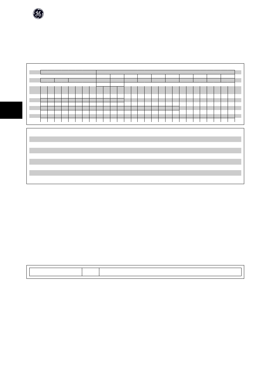
5.3 PCV Parameter Access
Parameter access via the PCV channel is performed by the PROFIBUS DP V0 cyclical data exchange, where the PCV channel is part of the PPOs described in the
chapter How to Control the Frequency Converter.
PCV
PCD
1
2
3
4
5
6
7
8
9
10
PCA
IND
PVA
CTW
MRV
PCD
PCD
PCD
PCD
PCD
PCD
PCD
PCD
STW
MAV
Byte
no.
1
2
3
4
5
6
7
8
9
10 11 12 13 14 15 16 17 18 19 20 21 22 23 24 25 26 27 28
Type 1:
Type 2:
Type 5:
PCV:
Parameter Characteristics Value
PCD:
Process Data
PCA:
Parameter Characteristics (Bytes 1, 2)
IND:
Sub index (Byte 3. Byte 4 is not used)
PVA:
Parameter value (Bytes 5 to 8)
CTW:
Control word
STW:
Status word
MRV:
Main reference value
MAV:
Main actual value (Actual output frequency)
Using the PCV channel it is possible to read and write parameter values, as well as readout of a number of describing attributes of each parameter.
5.3.1 PCA Handling
The PCA part of PPO types 1, 2 and 5 can handle several tasks. The master can control and supervise parameters and request a response from the slave, whereas
the slave can respond to a request from the master.
Requests and responses is a handshake procedure and cannot be batched, meaning that if the master sends out a read/write request, it has to wait for the
response, before it sends a new request. The request or response data value will be limited to maximum 4 bytes, which implies that text strings are not transferable.
For further information, please see the Application Examples chapter.
5.3.2 PCA - Parameter Characteristics
15
14
13
12
11
10
9
8
7
6
5
4
3
2
1
0
RC
SMP
PNU
RC: Request/response characteristics (Range 0..15)
SMP: Spontaneous Messag (Not supported)
PNU : Parameter no. (Range 1..1999)
AF-650 GP/AF-600 FP Profibus DP Operating Instructions
50
5