GE Industrial Solutions AF-600 FP Profibus DP User Manual
Page 19
Open a Project, set up the Hardware and add a PROFIBUS Master system.
Select AF-6 Series then drag and drop it onto the PROFIBUS in the Hardware
diagram.
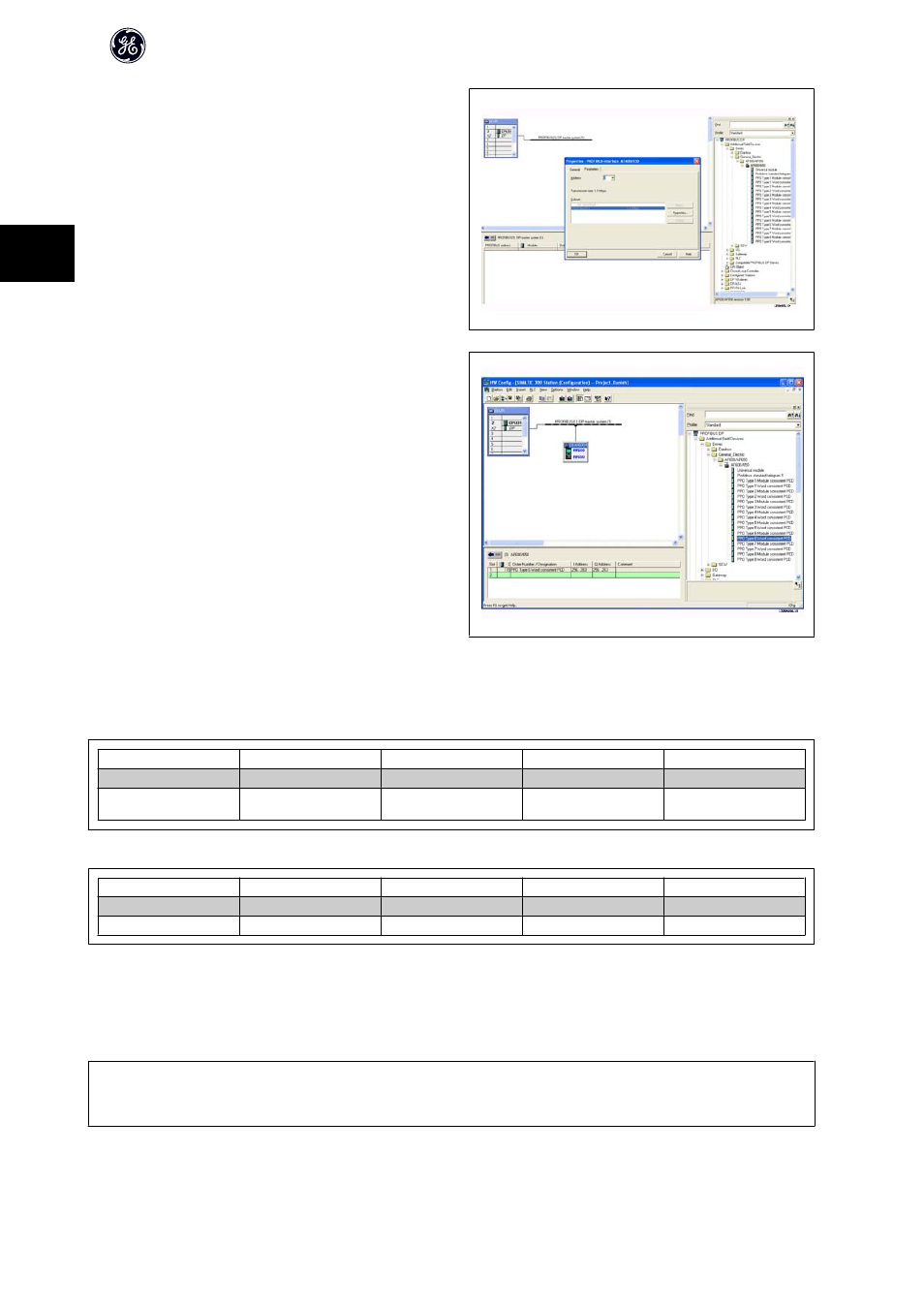
A window for the address of the AF-6 Series now appears. Select the address
from the scroll-down list. Note that this address setting must match the pre-
vious address setting in par. PB-18 Node Address.
The next step is to set up the peripheral input and output data. Data set up
in the peripheral area is transmitted cyclically via PPO types. In the example
below, a PPO type 6 Word consistent is dragged and dropped to the first slot.
See the PPO types section in How to Control the Frequency Converter for more
information.
The configuration tool automatically assigns addresses in the peripheral address area. In this example the input and output area have the following configuration:
PPO type 6:
PCD word number
1
2
3
4
Input address
256-257
258-259
260-261
262-263
Set-up
STW
MAV
Par. PB-16.2
Par. PB-16.3
Table 3.1: PCD read (Drive to PLC)
PCD word number
1
2
3
4
Output address
256-257
258-259
260-261
262-263
Set-up
CTW
MRV
Par. PB-15.2
Par. PB-15.3
Table 3.2: PCD write (PLC to Drive)
For Profibus SW version 2.x and higher, Auto-configuration of process data is supported. This feature makes it possible to configure the process data (par.
PB-15 PCD Write Configuration and par. PB-16 PCD Read Configuration) from the PLC/Master. To use Autoconfig, make sure the feature under DP slave Proper-
ties is enabled.
NB!
DP V1 diagnostics is supported for Profibus SW version 2 and higner. This means that the default setting of the Profibus option is DP V1 diagnostics. If DP V0
diagnostics are required, the setting under DP slave Properties must be changed
Download the configuration file to the PLC. The PROFIBUS system should be able to go online and it will start to exchange data when the PLC is set to Run mode.
AF-650 GP/AF-600 FP Profibus DP Operating Instructions
18
3