3 configure the frequency converter – GE Industrial Solutions AF-600 FP Profibus DP User Manual
Page 20
3.3 Configure the Frequency Converter
3.3.1 Drive Parameters
Pay particular attention to the following parameters when configuring the frequency converter with a PROFIBUS interface.
•
par. K-40 [Hand] Button on Keypad. If the Hand button on the frequency converter is activated, control of the drive via the PROFIBUS interface is disabled
•
After an initial power up the frequency converter will automatically detect whether a network option is installed in slot A, and set par. O-02 Control Word
Source to [Option A]. If an option is added or changed in or removed from an already commissioned drive, it will not change par. O-02 Control Word
Source but enter Trip Mode, and the drive will display an error
•
par. O-10 Control Word Profile. Choose between the GE Drive Profile and the PROFIdrive profile
•
par. O-50 Coasting Select to par. O-56 Preset Reference Select. Selection of how to gate PROFIBUS control commands with digital input command of the
control module.
NB!
When par. O-01 Control Site is set to [2] Control word only, then the settings in par. O-50 Coasting Select to par. O-56 Preset Reference Select will be overruled,
and all act on Bus-control.
•
par. O-03 Control Word Timeout Time to par. O-05 End-of-Timeout Function. The reaction in the event of a network time out is set via these parameters
•
par. PB-18 Node Address
•
par. O-07 Diagnosis Trigger
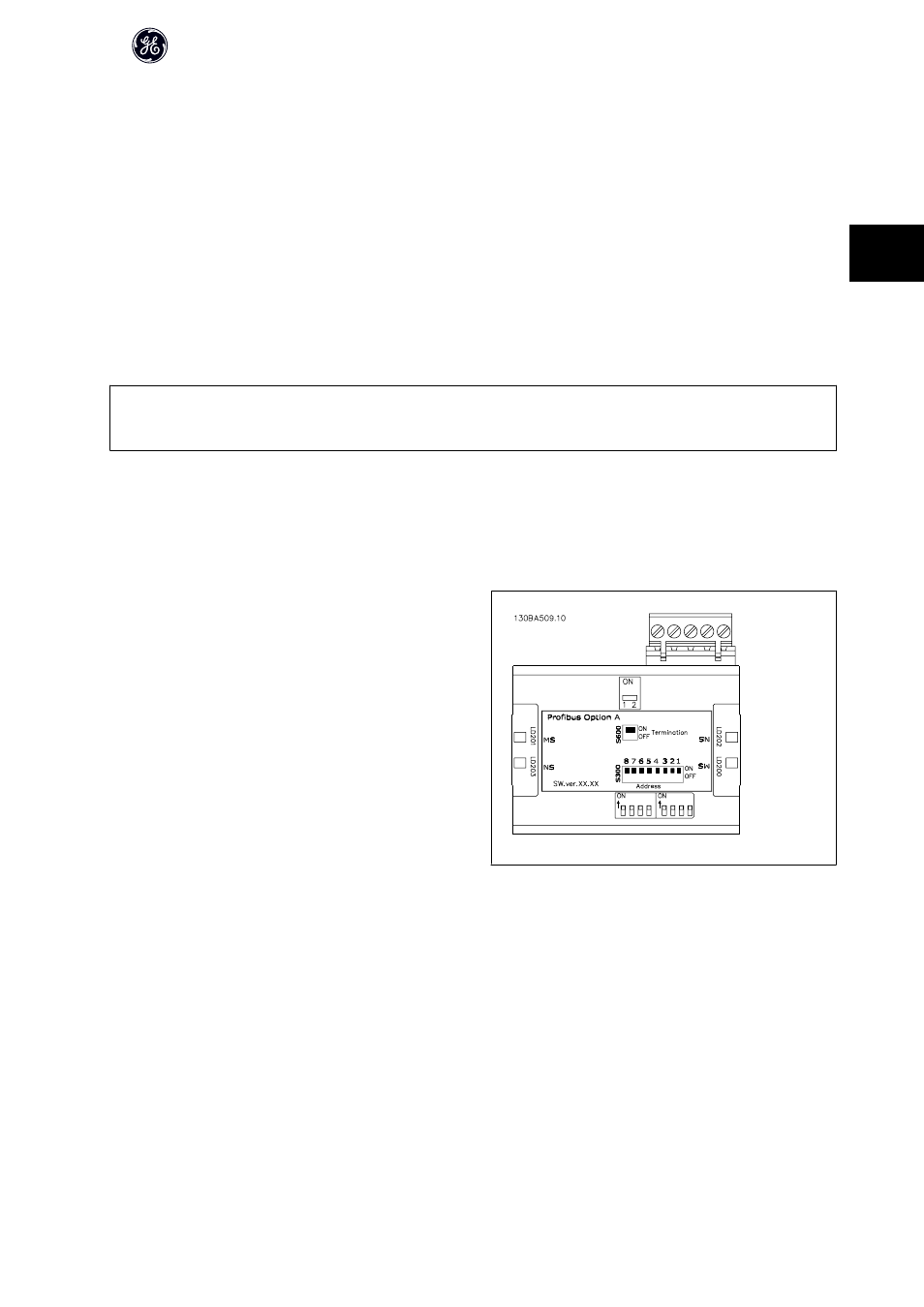
3.3.2 LEDs
The two bi-colour LEDs in the PROFIBUS module indicate the status of PRO-
FIBUS communication
The LED marked NS indicates the network status, i.e. the cyclical communi-
cation to the PROFIBUS master. When this light shows constant green, then
data exchange between the master and the frequency converter is active.
The LED marked MS indicates the module status, i.e. acyclical DP V1 commu-
nication from either a PROFIBUS master class 1 (PLC) or a master class 2
(DCT-10). When this light shows constant green, then DP V1 communication
from master classes 1 and 2 is active.
For details of the full range of communications status indicated by the LEDs,
please refer to the Troubleshooting chapter.
AF-650 GP/AF-600 FP Profibus DP Operating Instructions
19
3