GE Industrial Solutions AF-600 FP Profibus DP User Manual
Page 13
2.1.6 Connecting the Network
Proper termination of the network is essential. A mismatch of impedance may
result in reflections on the line that will corrupt data transmission.
-
The Profibus DP Communications Module has a suitable termina-
tion, activated by switch 1 located on the Profibus option. The
switches must be on to terminate the network. The factory setting
is off.
-
Nodes at the physical ends of each segment must be terminated.
-
When power to the Profibus DP Communications Module is down,
please note that the termination is still active, although not func-
tional.
-
Most masters and repeaters are equipped with their own termina-
tion.
-
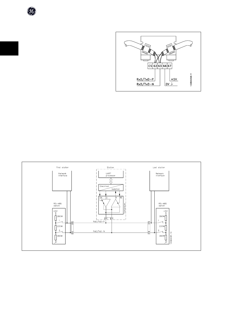
If an external termination circuit consisting of three resistors is con-
nected to the network, a 5V DC power supply must be used. Terminal
66 and 67 can be used for this.
-
The CS-pin on the Profibus connector is Control Select. When option
goes into active state and sends a message, the CS pin goes high
(+5 Volts). This can be used to control optical transmitters etc. or for
triggering measurement equipment like an oscilloscope.
-
D-sub 9 connector.
If desired, a D-sub 9 adaptor can be added as an option.
N.B.: If the D-sub 9 adaptor is used, please be aware that the ter-
mination switch on the Profibus option is set to OFF, to avoid double
termination. as the Profibus D-sub 9 connector also features a ter-
mination switch.
Illustration 2.1: 62 = RxD/TxD-P red cable (Siemens B)
63 = RxD/TxD-N green cable (Siemens A)
66 and 67 are for use with external terminator resistor only
AF-650 GP/AF-600 FP Profibus DP Operating Instructions
12
2