8 how to use the dp v1 acyclical parameter channel – GE Industrial Solutions AF-600 FP Profibus DP User Manual
Page 45
5.2.8 How to Use the DP V1 Acyclical Parameter Channel
The PROFIdrive Parameter Channel should be used for read and write for AF-650 GP & AF-600 FP drive parameters. The table below shows the structure of the
PROFIdrive Parameter Channel. Using this it is possible to access the following drive parameter values and attributes:
-
Parameter values of simple variable, array and visible string
-
Parameter description elements such as type, min./max. value, etc.
-
Descriptive text for parameter values
-
Access to multiple parameters in one message is also possible
PROFIBUS DP V1 message for read/write from or to a drive parameter:
PROFIBUS
Message
Header
Data Unit
PROFIBUS Message
Trailer
DP V1
Command/response
PROFIdrive V3.0 Parameter Channel
DU
0
DU
1
DU
2
DU
3
Req. / Res. Header
Data
The following table shows the principle structure of the PROFIdrive Parameter
Channel.
The DP V1 Parameter Request message consists of 3 data blocks:
-
a Request Header, which defines the kind of request (Read or Write),
and the number of parameters to access. The master sets the Re-
quest Reference, and uses this information to evaluate the response
-
an address field, where all addressing attributes of the desired pa-
rameters are defined
-
a data field, where all parameter data values are placed
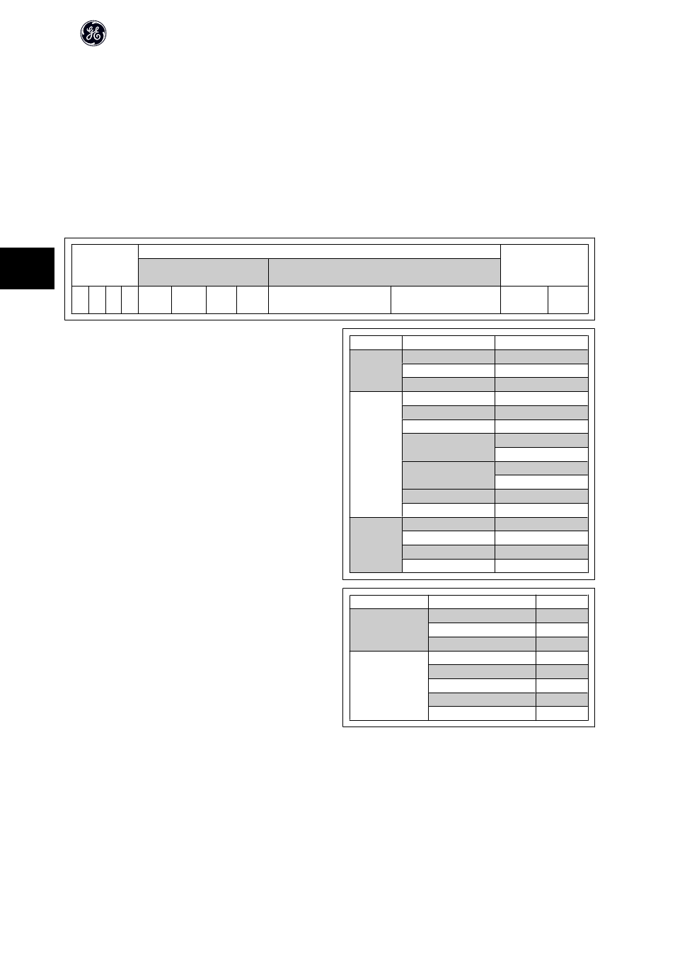
DP V1
Parameter request
Byte no.
Request
header
Request reference
0
Request ID
1
Axis
2
Address field
No. of parameters
3
Attribute
4
No. of elements
5
Parameter no.
6
7
Sub index
8
9
n'th parameter no.
4+6*(n-1)
...
Data field
Data format
4+6*n
No. of values
(4+6*n)+1
Values
(4+6*n)+2
n'th data value
...
The DP V1 Parameter response message consists of 2 data blocks:
-
A response header, which indicates if the request is performed
without errors (Response ID), the number of parameters, and the
Request Reference set by the master within the corresponding re-
quest message
-
A Data field, where the requested data are placed. If one or more
internal requests have failed, an Error Code is placed instead of the
data values
DP V1
Parameter response
Byte no.
Response header
Request ref. mirrored
0
Response ID
1
Axis mirrored
2
Parameter values
No. of parameters
3
Format
4
No. of values
5
Values of error values
6
n'th parameter value
...
As the response message does not include parameter addressing information, the master must identify the structure of the response data from the request
message.
AF-650 GP/AF-600 FP Profibus DP Operating Instructions
44
5