4 profidrive control profile, 1 profidrive control profile – GE Industrial Solutions AF-600 FP Profibus DP User Manual
Page 27
4.4 PROFIdrive Control Profile
4.4.1 PROFIdrive Control Profile
This section describes the functionality of the control word and status word in the PROFIdrive profile. Select this profile by setting par. O-10 Control Word Profile.
4.4.2 Control Word according to PROFIdrive Profile (CTW)
The Control word is used to send commands from a master (e.g. a PC) to a
slave.
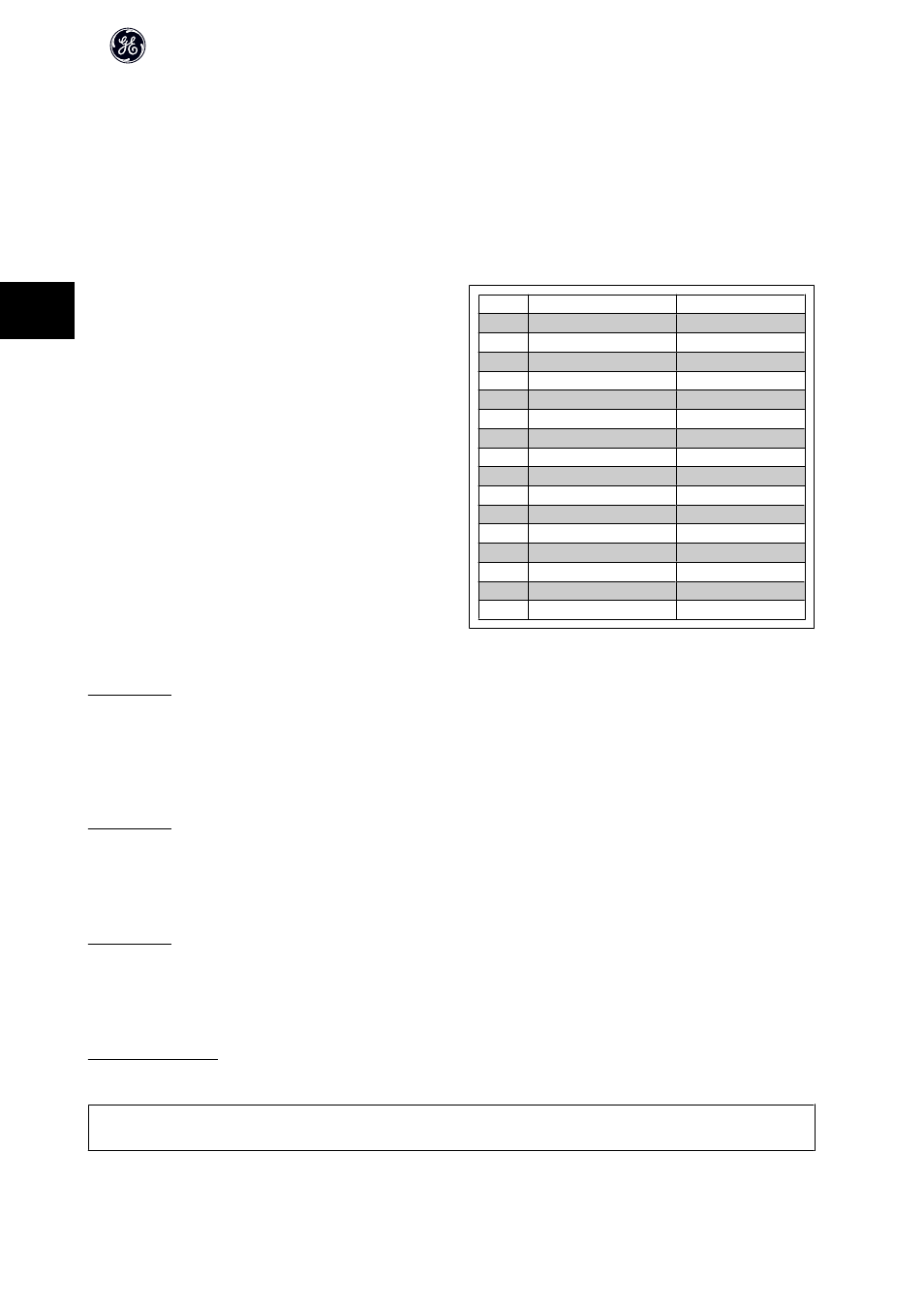
Bit
Bit = 0
Bit = 1
00
OFF 1
ON 1
01
OFF 2
ON 2
02
OFF 3
ON 3
03
Coasting
No coasting
04
Quick stop
Accel/Decel
05
Hold frequency output
Use Accel/Decel
06
Accel/Decel stop
Start
07
No function
Reset
08
Jog 1 OFF
Jog 1 ON
09
Jog 2 OFF
Jog 2 ON
10
Data invalid
Data valid
11
No function
Slow down
12
No function
Catch up
13
Parameter set-up
Selection lsb
14
Parameter set-up
Selection msb
15
No function
Reverse
Explanation of the Control Bits
Bit 00, OFF 1/ON 1
Normal ramp stop using the ramp times of the actual selected ramp.
Bit 00 = "0" leads to the stop and activation of the output relay 1 or 2 if the output frequency is 0 Hz and if [Relay 123] has been selected in par. E-24 Function
Relay.
When bit 00 = "1", the frequency converter is in State 1: “Switching on inhibited”.
Please refer to the PROFIdrive State Transition Diagram, at the end of this section.
Bit 01, OFF 2/ON 2
Coasting stop
When bit 01 = "0", a coasting stop and activation of the output relay 1 or 2 occurs if the output frequency is 0 Hz and if [Relay 123] has been selected in par.
E-24 Function Relay.
When bit 01 = "1", the frequency converter is in State 1: “Switching on inhibited”. Please refer to the PROFIdrive State Transition Diagram, at the end of this section.
Bit 02, OFF 3/ON 3
Quick stop using the ramp time of par. C-23 Quick Stop Decel Time. When bit 02 = "0", a quick stop and activation of the output relay 1 or 2 occurs if the output
frequency is 0 Hz and if [Relay 123] has been selected in par. E-24 Function Relay.
When bit 02 = "1", the frequency converter is in State 1: “Switching on inhibited”.
Please refer to the PROFIdrive State Transition Diagram, at the end of this section.
Bit 03, Coasting/No coasting
Coasting stop Bit 03 = "0" leads to a stop. When bit 03 = "1", the frequency converter can start if the other start conditions are satisfied.
NB!
The selection in par. O-50 Coasting Select Coasting select determines how bit 03 is linked with the corresponding function of the digital inputs.
AF-650 GP/AF-600 FP Profibus DP Operating Instructions
26
4