Spi timing characteristics, Figure 146, Atmega16(l) – Rainbow Electronics ATmega64L User Manual
Page 286
286
ATmega16(L)
2466B–09/01
5. This requirement applies to all ATmega16 2-wire Serial Interface operation. Other
devices connected to the 2-wire Serial Bus need only obey the general f
SCL
requirement.
6. The actual low period generated by the ATmega16 2-wire Serial Interface is (1/f
SCL
-
2/f
CK
), thus f
CK
must be greater than 6 MHz for the low time requirement to be strictly
met at f
SCL
= 100 kHz.
7. The actual low period generated by the ATmega16 2-wire Serial Interface is (1/f
SCL
-
2/f
CK
), thus the low time requirement will not be strictly met for f
SCL
> 308 kHz when
f
CK
= 8 MHz. Still, ATmega16 devices connected to the bus may communicate at full
speed (400 kHz) with other ATmega16 devices, as well as any other device with a
proper t
LOW
acceptance margin.
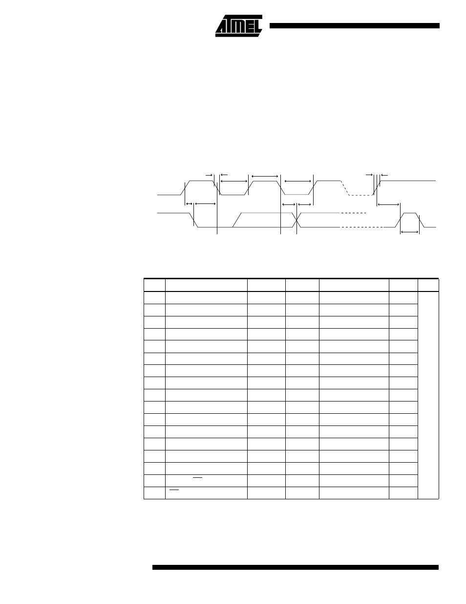
Figure 146. 2-wire Serial Bus Timing
SPI Timing
Characteristics
See Figure 147 and Figure 148 for details.
t
SU;STA
t
LOW
t
HIGH
t
LOW
t
of
t
HD;STA
t
HD;DAT
t
SU;DAT
t
SU;STO
t
BUF
SCL
SDA
t
r
Table 122. SPI timing parameters
Description
Mode
Min
Typ
Max
1
SCK period
Master
ns
2
SCK high/low
Master
50% duty cycle
3
Rise/Fall time
Master
TBD
4
Setup
Master
TBD
5
Hold
Master
TBD
6
Out to SCK
Master
TBD
7
SCK to out
Master
TBD
8
SCK to out high
Master
TBD
9
SS low to out
Slave
TBD
10
SCK period
Slave
4 • t
ck
TBD
11
SCK high/low
Slave
2 • t
ck
TBD
12
Rise/Fall time
Slave
TBD
13
Setup
Slave
TBD
14
Hold
Slave
TBD
15
SCK to out
Slave
TBD
16
SCK to SS high
Slave
TBD
17
SS high to tri-state
Slave
TBD