Table 47, Atmega16(l) – Rainbow Electronics ATmega64L User Manual
Page 106
106
ATmega16(L)
2466B–09/01
Note:
1. The CTC1 and PWM11:0 bit definition names are obsolete. Use the
WGM
12:0 definitions. However, the functionality and
location of these bits are compatible with previous versions of the timer.
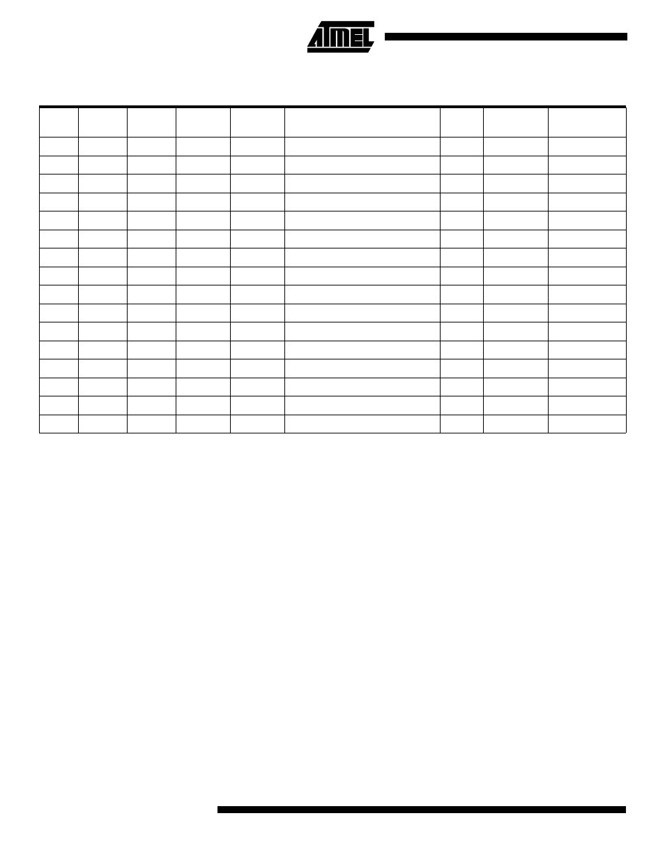
Table 47. Waveform Generation Mode Bit Description
Mode
WGM13
WGM12
(CTC1)
WGM11
(PWM11)
WGM10
(PWM10)
Timer/Counter Mode of Operation
TOP
Update of
OCR1
x
TOV1 Flag Set
on
0
0
0
0
0
Normal
0xFFFF
Immediate
MAX
1
0
0
0
1
PWM, Phase Correct, 8-bit
0x00FF
TOP
BOTTOM
2
0
0
1
0
PWM, Phase Correct, 9-bit
0x01FF
TOP
BOTTOM
3
0
0
1
1
PWM, Phase Correct, 10-bit
0x03FF
TOP
BOTTOM
4
0
1
0
0
CTC
OCR1A
Immediate
MAX
5
0
1
0
1
Fast PWM, 8-bit
0x00FF
TOP
TOP
6
0
1
1
0
Fast PWM, 9-bit
0x01FF
TOP
TOP
7
0
1
1
1
Fast PWM, 10-bit
0x03FF
TOP
TOP
8
1
0
0
0
PWM, Phase and Frequency Correct
ICR1
BOTTOM
BOTTOM
9
1
0
0
1
PWM, Phase and Frequency Correct
OCR1A
BOTTOM
BOTTOM
10
1
0
1
0
PWM, Phase Correct
ICR1
TOP
BOTTOM
11
1
0
1
1
PWM, Phase Correct
OCR1A
TOP
BOTTOM
12
1
1
0
0
CTC
ICR1
Immediate
MAX
13
1
1
0
1
Reserved
–
–
–
14
1
1
1
0
Fast PWM
ICR1
TOP
TOP
15
1
1
1
1
Fast PWM
OCR1A
TOP
TOP
- MAX5151 (16 pages)
- MAXQ3108 (64 pages)
- MAX5661 (39 pages)
- MAX6691 (7 pages)
- MAX5362 (12 pages)
- ADC10158 (26 pages)
- MAX8922L (14 pages)
- MAX8596Z (8 pages)
- MAX7491 (18 pages)
- MAX15040 (15 pages)
- MAX5177 (16 pages)
- ADC08138 (22 pages)
- MAX5961 (42 pages)
- T89C51RD2 (86 pages)
- MAX16055 (9 pages)
- MAX6659 (17 pages)
- ADC0820 (20 pages)
- MAX6678 (19 pages)
- MAX8884Z (15 pages)
- MAX16915 (9 pages)
- MAX8620 (18 pages)
- MAX5144 (12 pages)
- MAX6670 (8 pages)
- MAX8760 (39 pages)
- W78C32C (14 pages)
- MX7533 (8 pages)
- MAX8727 (13 pages)
- MAX9053 (15 pages)
- W78C54 (16 pages)
- MAX8614B (15 pages)
- W90N740 (219 pages)
- MAX6626 (13 pages)
- ADC10738 (30 pages)
- MAX17000 (31 pages)
- MAX5051 (21 pages)
- MAXQ1004 (18 pages)
- MAX6871 (51 pages)
- MX7847 (12 pages)
- MAX6608 (6 pages)
- MAX17083 (15 pages)
- MAX6641 (17 pages)
- MAX5251 (16 pages)
- MAX6338 (8 pages)
- MAX6690 (16 pages)
- MAX8668 (18 pages)