Reset and interrupt handling, Atmega16(l) – Rainbow Electronics ATmega64L User Manual
Page 11
11
ATmega16(L)
2466B–09/01
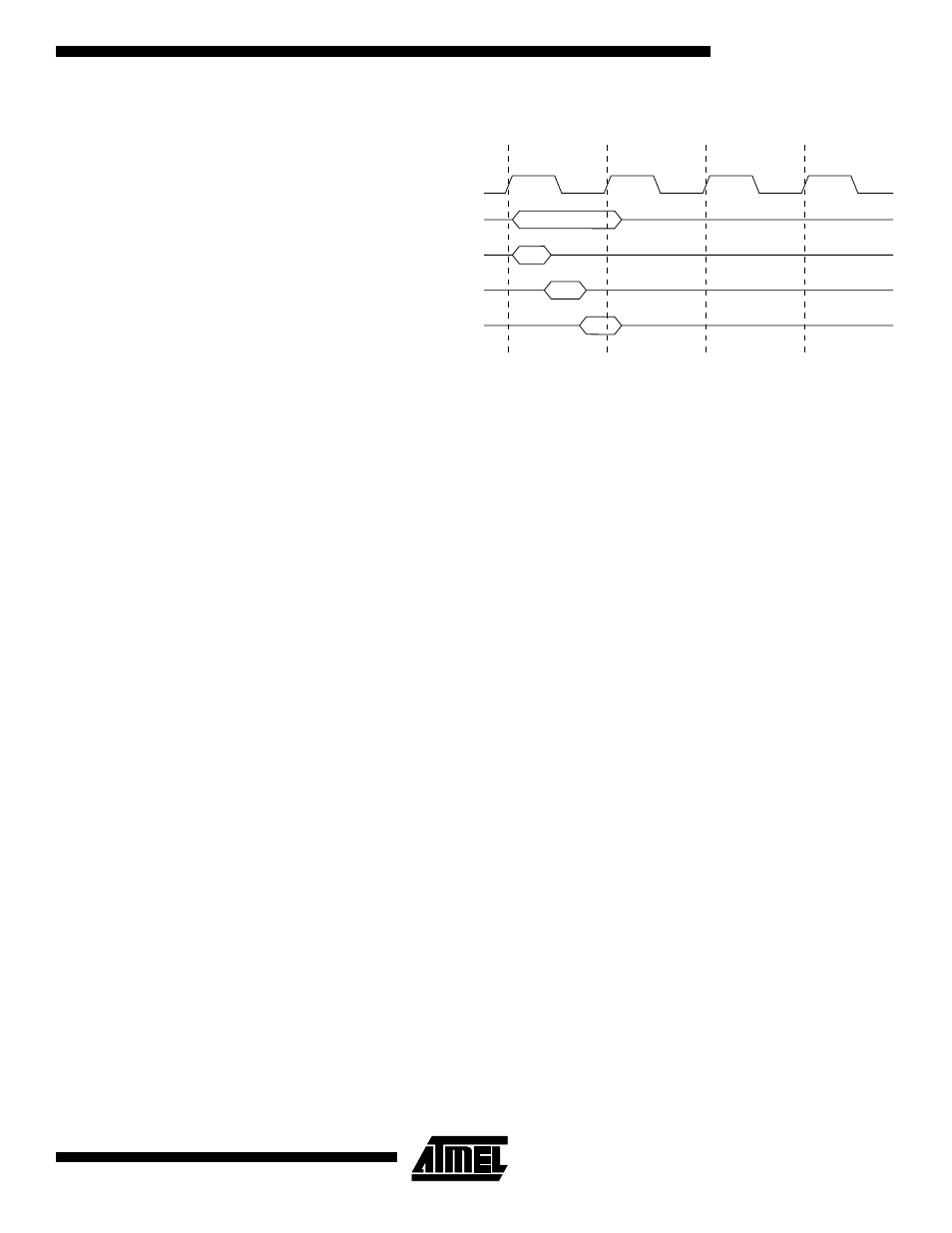
Figure 7. Single Cycle ALU Operation
Reset and Interrupt
Handling
The AVR provides several different interrupt sources. These interrupts and the separate
reset vector each have a separate program vector in the program memory space. All
interrupts are assigned individual enable bits which must be written logic one together
with the Global Interrupt Enable bit in the Status Register in order to enable the interrupt.
Depending on the program counter value, interrupts may be automatically disabled
when Boot Lock bits BLB02 or BLB12 are programmed. This feature improves software
security. See the section “Memory Programming” on page 253 for details.
The lowest addresses in the program memory space are by default defined as the Reset
and Interrupt vectors. The complete list of vectors is shown in “Interrupts” on page 42.
The list also determines the priority levels of the different interrupts. The lower the
address the higher is the priority level. RESET has the highest priority, and next is INT0
– the External Interrupt Request 0. The interrupt vectors can be moved to the start of the
boot Flash section by setting the IVSEL bit in the General Interrupt Control Register
(GICR). Refer to “Interrupts” on page 42 for more information. The Reset vector can
also be moved to the start of the boot Flash section by programming the BOOTRST
fuse, see “Boot Loader Support – Read-While-Write Self-Programming” on page 240.
When an interrupt occurs, the Global Interrupt Enable I-bit is cleared and all interrupts
are disabled. The user software can write logic one to the I-bit to enable nested inter-
rupts. All enabled interrupts can then interrupt the current interrupt routine. The I-bit is
automatically set when a Return from Interrupt instruction – RETI – is executed.
There are basically two types of interrupts. The first type is triggered by an event that
sets the interrupt flag. For these interrupts, the Program Counter is vectored to the
actual interrupt vector in order to execute the interrupt handling routine, and hardware
clears the corresponding interrupt flag. Interrupt flags can also be cleared by writing a
logic one to the flag bit position(s) to be cleared. If an interrupt condition occurs while the
corresponding interrupt enable bit is cleared, the interrupt flag will be set and remem-
bered until the interrupt is enabled, or the flag is cleared by software. Similarly, if one or
more interrupt conditions occur while the global interrupt enable bit is cleared, the corre-
sponding interrupt flag(s) will be set and remembered until the global interrupt enable bit
is set, and will then be executed by order of priority.
The second type of interrupts will trigger as long as the interrupt condition is present.
These interrupts do not necessarily have interrupt flags. If the interrupt condition disap-
pears before the interrupt is enabled, the interrupt will not be triggered.
When the AVR exits from an interrupt, it will always return to the main program and exe-
cute one more instruction before any pending interrupt is served.
Total Execution Time
Register Operands Fetch
ALU Operation Execute
Result Write Back
T1
T2
T3
T4
clk
CPU