Detailed description, Frequency synthesis, Crystal reference oscillator – Rainbow Electronics AT86RF211 User Manual
Page 7: Synthesizer
7
AT86RF211
1942C–WIRE–06/02
Detailed Description
Frequency Synthesis
Crystal Reference Oscillator
The reference clock is based on a classical Colpitts architecture with three external
capacitors.
An XTAL with load capacitor in the range of 10 pF - 20 pF is recommended. The bias
circuitry of the oscillator is optimized to produce a low drive level for the XTAL. This
reduces XTAL aging. Any standard, parallel mode 10.245 MHz or 20.945 MHz crystal
can be used.
Note:
The PLL is activated only when the oscillator is stabilized.
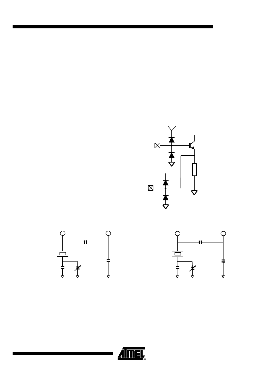
Figure 5. Crystal Oscillator Inputs
Figure 6. Typical Networks
Notes:
1. Various load capacitance (C
L
) crystals can be used. In case C
L
differs of 16 pF or 20 pF, the surrounding network (C1, C2)
must be re-calculated.
2. Thanks to the fine steps of the synthesizer (200 Hz), the trimmer capacitor can be replaced by a software adjustment.
Synthesizer
A high-speed, high-resolution multi-loop synthesizer is integrated. The synthesizer can
operate within two frequency bands: 400 MHz to 480 MHz and 800 MHz to 950 MHz. All
channels in these two bands can be selected through software programming (registers
F0 to F3). All circuitry is on-chip with the exception of the PLL loop filter. The phase
comparison is made thanks to a charge pump topology. Typical charge pump current is
225 µA.
XTAL1
XTAL2
C1 = 82 pF
C2 = 56 pF
XTAL1
XTAL2
CL = 16 pF
15 pF
6.5/30 pF
C1 = 68 pF
XTAL1
XTAL2
CL = 20 pF
33 pF
6.5/30 pF
C2 = 68 pF
(1)
(2)
(1)
(2)