Synthesizer specification, Receiver specification – Rainbow Electronics AT86RF211 User Manual
Page 43
43
AT86RF211
1942C–WIRE–06/02
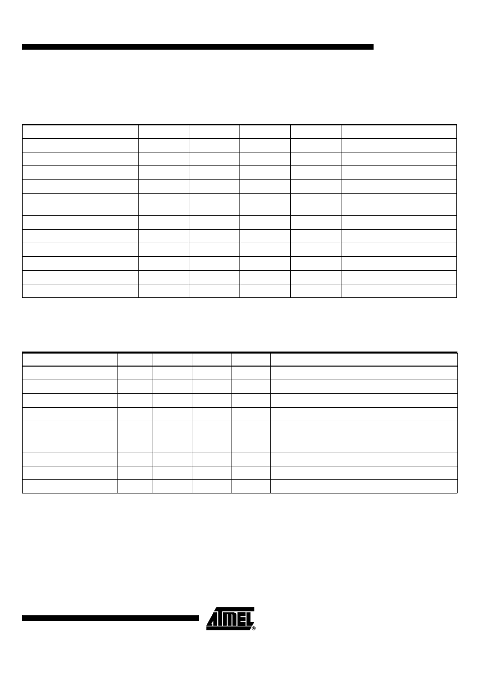
Synthesizer
Specification
Unless otherwise specified, data is given for T = 25°C, V
SUPPLY
= 2.7V
ii
Notes:
1. Crystal frequency can be slightly changed but since IF2 = IF1 - Crystal frequency, IF2 will shift and must remain within the
IF2 filter and discriminator bandwidth.
2. With the "typical implementation" loop filter.
Receiver Specification
Unless otherwise specified, data is given for T = 25°C V
SUPPLY
= 2.7V
Note:
1. The overall sensitivity depends on measurements conditions and external components, i.e.:
-100 dBm for BW = ± 10 kHz,
∆
F = ± 7.5 kHz, Brate = 4800 bps with RF switch used and external SAW filter
Parameter
Min
Typ
Max
Unit
Comments
Frequency Range
400
480
MHz
Digital programming
Frequency Range
800
950
MHz
Digital programming
Crystal Frequency
10.235
10.245
10.255
MHz
IF 1 = 10.7 MHz
Crystal Frequency
20.925
20.945
20.965
MHz
IF 1 = 21.4 MHz
Oscillator Settling Time
5
8
ms
Depending on crystal
specifications
Lock Time
300
µs
From oscillator settling
Lock Time
30
µs
100 kHz shift
Phase Noise 400 to 480 MHz
-80
dBc/Hz
At 10 kHz from the carrier
Phase Noise 800 to 950 MHz
-75
dBc/Hz
At 10 kHz from the carrier
Phase Noise 400 to 480 MHz
-91
dBc/Hz
At 100 kHz from the carrier
Phase Noise 800 to 950 MHz
-86
dBc/Hz
At 100 kHz from the carrier
Parameter
Min
Typ
Max
Unit
Comments
IF1
10.7
MHz
21.4 MHz also possible
IF1 Filter Impedance
330
Ω
IF2
455
kHz
IF2 Filter Impedance
1700
Ω
FSK Sensitivity
-105
dBm
Typical performance with a BER of 1% at input pin
RXIN (45). BW = ± 10 kHz,
∆
F = ± 7.5 kHz; Brate =
4800 bps
Noise Figure
15
dB
Input matched, complete RX chain
Input IP3
-15
dBm
Max Input Power
-5
dBm
BER < 10%