Power amplification – Rainbow Electronics AT86RF211 User Manual
Page 20
20
AT86RF211
1942C–WIRE–06/02
Power Amplification
The Power Amplifier has been built to deliver more than +10 dBm, i.e. 10 mW in the
three popular frequency bands. This power level is intended to be measured on the
aerial port with a correct output matching network. Note that a correct calculation of the
matching network guarantees an optimal power efficiency.
Naturally, the greater the PA output voltage swing, the better the power efficiency. As
the PA output is supplied through an inductor, a swing of 2 x V
DD
is possible. In practice,
due to saturation effects, the voltage swing is limited to approximately (2 x V
DD
) - 1V.
With a power supply voltage of 3V, the PA output voltage is 5V peak-to-peak, or
1.77 V
EFF
.
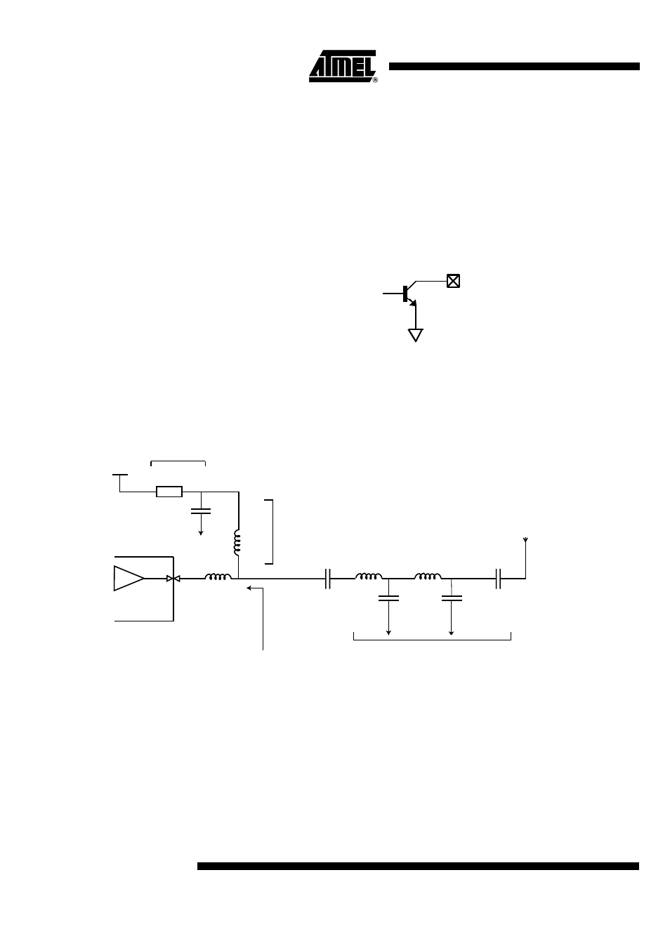
Figure 24. Output of the Power Amplifier
The PA must be correctly matched to deliver the best efficiency in terms of output power
and current consumption. Here is an example of the typical recommended output net-
work in the 868 MHz band:
Figure 25. Output Matching at 868 MHz
Note:
The filter is designed to meet relevant regulations. Please refer to application note for details.
A benefit of this network is to filter the output signal harmonic levels; hence it can be
designed to meet a particular regulation.
It is mandatory to implement low impedance grounding techniques. Excessive inductor
values to ground will not only limit the PA output voltage swing, but may also trigger RF
instability. Board design is vital to avoid parasitic loss when high output power is needed
(direct short connection to a single low impedance ground plane).
RF
PA output
1.5 nH
12 nH
Vcc
Power supply
filtering
Supply
inductor
50
Ω
aerial
~ 50
Ω matched filtering