Fsk demodulator – Rainbow Electronics AT86RF211 User Manual
Page 16
16
AT86RF211
1942C–WIRE–06/02
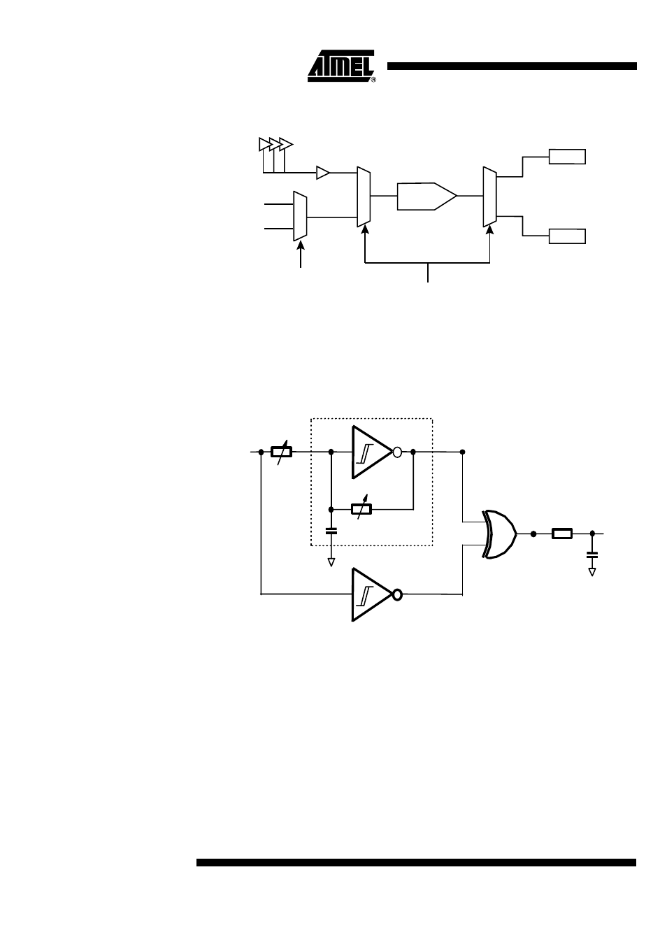
Figure 19. ADC Converter Input Selection
Note:
For voltage measurement, the LSB weighs 85 mV and the reference voltage is 1.25V.
The ADC measuring the RSSI can be turned into voltage or discriminator output DC
level measurement.
FSK Demodulator
Its structure is based on an oscillator:
Figure 20. Schematic of the FSK demodulator
The oscillator’s natural frequency is F
D
and it actually oscillates at the Fin frequency.
The signal at the output of the oscillator (point A) is proportional to the frequency differ-
ence between Fin and F
D
. The XOR function translates the difference into a pulse duty
cycle (point B).Thereafter by low-pass filtering of the signal is obtained a mean voltage
of the signal (point C).
The architecture of this demodulation is thereby analog and allows the transmission of
continuous data stream of the same value as the output voltage is proportional to the
input frequency. Thus it is not mandatory to use Manchester encoding and the first bit is
correctly demodulated.
The oscillator feedback resistor controls the center frequency F
D
. It is adjusted accord-
ing to the output of a dummy FSK demodulator driven by a 455 kHz internal reference
frequency which is a division of the reference crystal. The discrete components con-
nected to pin 32 DISCFILT are the loop filter of the PLL stabilizing the 455 kHz signal.
M
U
X
M
U
X
M
U
X
Voltage
RSSI
ADC
MRSSI
MVCC
STATUS register
CTRL1[24]
CTRL1[1]
Vcc supply
DISCOUT
(MOFFSET)
oscillator
Fin
A
B
C
FD
RBW